Building a working Cobblebot gantry
Posted: Wed Aug 12, 2015 10:41 pm
by neveroddoreven
UPDATE: I am using Weldingrod Bot design these days using the old
Cobblebot parts plus additional parts and upgraded components as
detailed on my Weldingrod Bot make on Thingiverse. For folks finally getting
around to their build, or those rebuilding from scratch, consider the Welding Rod
Bot design instead.
https://www.thingiverse.com/make:785594
--- ORIGINAL POST BELOW ---
UPDATE: I've gotten
to a complete first draft state. I have modified nearly all sections in the
last week, and updated the config file too. Please have a read, and send me
notes either as replies or as PMs.
Here are the steps that I took to build my working printer, deviating as little
from the original design in Cobblebot's V1.1 instructions as I could. I have a
1B from my December EB pledge, and I recently purchased an unused 1A kit
offline from another backer who decided they didn't need one any longer. For
the benefit of the community, I am reliving my 1B build experience using the 1A
parts, and publishing my steps here. Forgive that they will take a week or so
to fully publish -- I don't want to get ahead of a section before I actually
re-live it myself with the 1A kit.
Cobblebot/anyone, please adopt whatever you like from this, these tips are free
for all purposes from me to the world, however if you redistribute the
directions as written in full or in part, please credit me (Jason Frazier) as
the author. Some of this is recycled from other posts I made. If you see a
modification that you previously published and I recall seeing it and
plagiarizing, I'm happy to give credit if you drop me a PM. Mods, if I don't
update this after some weeks, feel free to take over and
update/revise/embellish for the community's benefit.
Disclaimer: I take no responsibility for anyone's personal or property damage
while attempting to implement these directions.
Re: Building a working Cobblebot gantry
Posted: Wed Aug 12, 2015 10:42 pm
by neveroddoreven
TL;DR
These instructions are crazy verbose. If you want abbreviated instructions that
also work for the impatient and determined mind, they already exist elsewhere
and they worked for me. This is for those who want more.
In addition to the Cobblebot Basic 1A or 1B parts, this is what I obtained from
elsewhere:
· 88x 5mm
ID 8mm OD 0.5mm thick fiber washers
-or- 46x 5mm ID 8mm OD 1.0mm thick metal washers
-or- another equivalent washer mentioned elsewhere in these forums that won't
bind the trucks
http://www.amazon.com/dp/B0006O5HJE
· For each
extruder, a one-meter length of 2mm ID 4mm OD PTFE tubing for my 1.75mm
filament (if using 3mm filament, I would have used what Cobblebot sent)
http://www.amazon.com/dp/B012T9HHDC
(two meters)
· One 40mm or 50mm 12VDC fan (the 10mm thin type) to cool your RAMPS board stepper drivers
· Two 14mm or longer M3 screws (socket cap head recommended)
· Four M5x20mm screws (socket cap head recommended)
· One M5x30mm screw (socket cap head recommended)
· (Optional) 8x M3x12mm screws (for a more secure fastening on the brass lead screw nuts)
· Eight M5 regular height nuts
· Eight more fasteners of any suitable type to mount my board, LCD etc to the top rail of the frame (I used M5x8mm pan head screws inverted with the heads slid into the rail channel, and an M5 nut on the outside to mount the items down to the screw stud -- cheaper than tee nuts, stable enough for electronics)
· At least ten more zip ties of similar size (2.5x100mm) as what was supplied by Cobblebot
· At least six medium size zip ties, roughly 5mm wide and at least 150mm long
· At least ten >=4 inch long cable twist ties, or pipe cleaners, or something flexible that you can tie a cable up with (zip ties will work later, but for now you want to reposition stuff and figure out your cable management)
· Three or four medium binder clips, clothespins, or similar to temporarily pin wire looms up and out of the way
· Two 20mm wide by 360 mm long strips of 1/4 inch thick pressboard (or other extremely flat manufactured wood product with no grain) (no crumbly particle board, it swells too much in humid weather)
· Enough PTFE grease to fill half a liquor shot glass, for lubricating the lead screws (Super-Lube 41160 in the USA, someone else can recommend another grease for elsewhere in the world), and a glove or truncated cotton swab/zip tie to apply it at the appropriate stage
· 1x small roll of quality lightweight electrical tape (the thick cheap stuff will work but might unpeel later)
· 1x reel of quality PLA filament from a reputable dealer (no cheap stuff for your inaugural and calibration prints) (preferably in medium gray so you can easily see all the issues)
· 1x USB A male to USB B male cable (the typical printer or hard drive USB cable) to connect your Mega board to your computer
· (Optional) Replacement DRV8825 stepper drivers for quieter operation in all axes, and twice the resolution in the X and Y axes
If you are upgrading to a silicone heated bed, you might buy/obtain:
· One 15 inch square aluminum build plate ONLY IF your own build plate is grossly deformed/warped. Minor deflections can be worked out and ultimately won't matter much once there is glass clamped on top. Check for deflections by sighting diagonally across the plate and examining a reflection of uniform flooring patterns such as carpet tile hardwoods etc, while spinning the plate around flat, you shoudn't see much change in the flooring pattern.
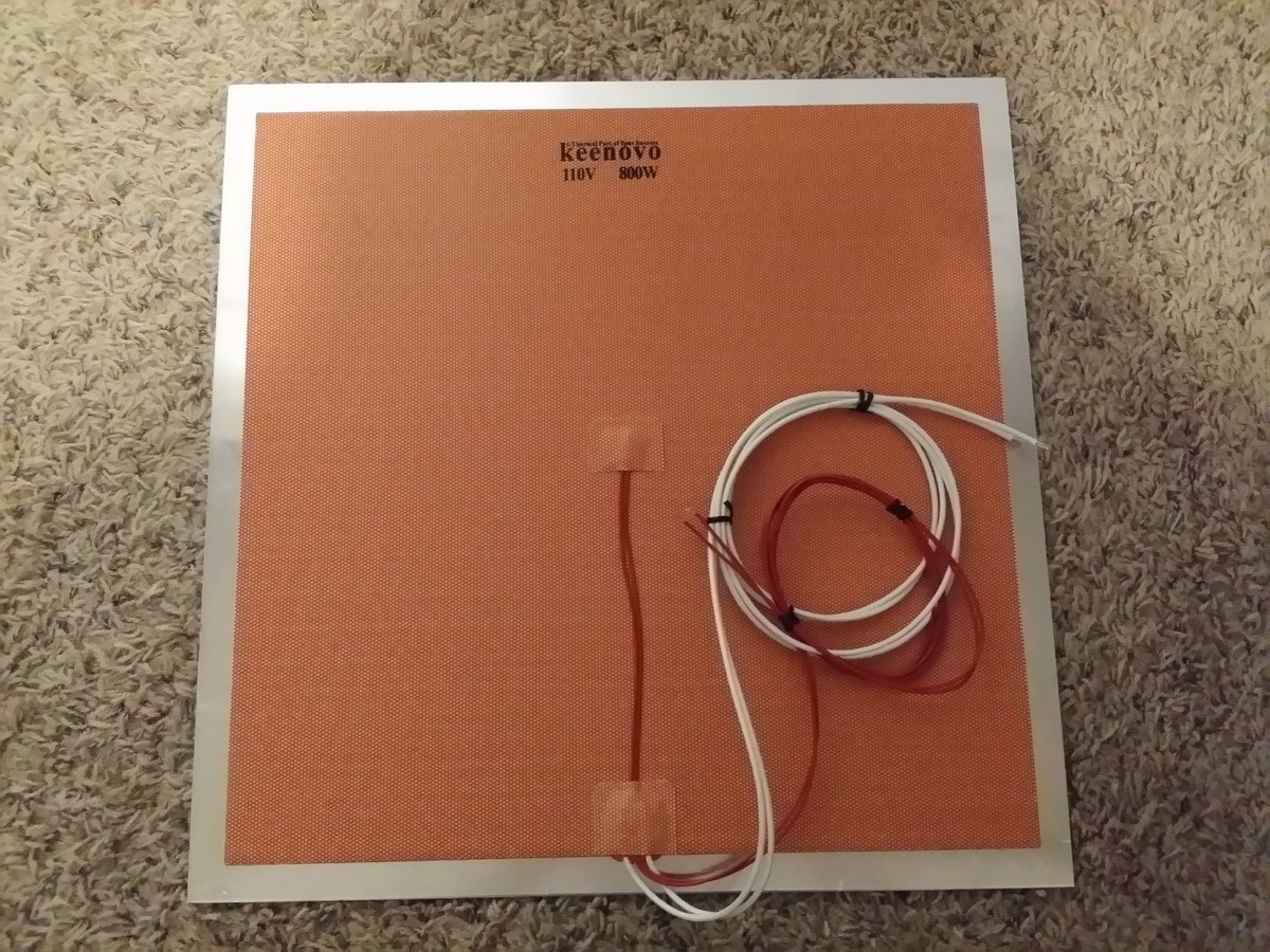
· One
350x350mm mains voltage powered silicone heater (for your country's voltage,
North Americans can use this link for 120VAC, others can contact Keenovo
directly or check their eBay sales)
http://www.amazon.com/dp/B011U919UO
· One pair
of 8x12x1 inch ceramic blankets (you can peel them apart into four halves and
get pretty good coverage) (or you can go cheaper and use itchy fiberglass
batts, but they are no good at smothering unexpected fires)
http://www.amazon.com/dp/B00GKTRMI8
· One
solid state relay to control your mains-powered heater
http://www.amazon.com/dp/B0087ZTN08
· One
three-prong mains power cord of suitable length to reach from the your mains
plug to the top of your printer (maybe cut the end off an old appliance or PC
power supply cable)
IMPORTANT -- THE PLUG AND YOUR WALL OUTLET MUST HAVE A WORKING GROUND PIN
· One 18AWG or better wire of 1 meter length (to ground the build plate to the mains plug)
· One butt splicer crimp connector and one spade or loop terminal crimp connector to attach the ground wire between the supply cord and the build plate
· At least three meters of two inch wide aluminum foil adhesive duct tape (do not use cloth based tapes)
· A 15 inch square sheet of 1/8 inch or 3mm glass with very little deviation/deflections in thickness, preferably borosilicate as it's virtually guaranteed to come rolled perfectly flat (or when taking your chances with regular glass, you can inspect for deflections as described above re: the build plate)
· Four No. 2 sized bulldog clips for holding the glass down to the build plate (medium binder clips work too but they stick up higher and can catch on your hotend parts)
You will need access to the following tools:
· Individual metric allen keys of 1.5mm, 2.0, 2.5mm and 3mm size (the integrated-handle ones will work poorly in some scenarios)
· An 8mm wrench (preferably socket wrench)
· Another 8mm wrench no thicker than 5mm (e.g. a simple spanner, or a mini-channel locks)
· A cheap
digital caliper with a depth measurement probe (Harbor Freight has them for
$15)
http://www.amazon.com/dp/B003MA08VQ
· A cheap voltmeter with any amount of accuracy in the 200-600 millivolt range
· A bench grinder, angle grinder, dremel grinding tool, or something like it (or a set of coarse files with time, sweat and courage)
· Channel locks or vise-grips to grasp and grind hot metal
· A cheap cloth belt ratcheting tie-down strap at least ten feet long
· Four identical length unused hardwood carpenter's pencils, or four of some other stick-like objects that are >160mm long by at least 10mm wide on one side. These sticks must be factory cut (not moulded) to an identical length -- it's for calibration, and you want them identically-sized to within 0.2mm (0.1 or less is even better)
· One hand-operated woodworking bar clamp or C-clamp, can be short (8 inches), should have plastic/rubber shoes over the jaws to protect surfaces
· A credit/debit card that you don't mind scratching up a little bit
Re: Building a working Cobblebot gantry
Posted: Wed Aug 12, 2015 10:42 pm
by neveroddoreven
Part 0: Read all of
these instruction posts, examine the pictures in the V1.1 Cobblebot
instructions, and inventory all your parts
Seriously! Do it! Including inventory of all the fasteners. And double check
that your extruder push fitting is the correct "4" mm push-fit
diameter.
Every time you start a new assembly section, be sure to set out exactly the
number of parts, screws, washers and nuts needed BEFORE you start assembling.
This helps catch unnecessary fastener waste before you get too far into
assembly.
Also, if a fastener does not want to thread easily, back it out and rotate
backwards until it clicks and seats itself, then thread it in. A few fasteners
might be imperfect and require a little effort to pilot them in. You already
have a few extra of all the M5 stuff, and can likely make do if one turns out
unusable.
A fair warning: There are several places in this document where it says that a
part or a fastener should face in a specific direction inside an assembly. This
is intentional and should not be taken lightly. If you have questions about
these design choices, please ask and I'll answer as best as I can.
Re: Building a working Cobblebot gantry
Posted: Sat Aug 15, 2015 2:19 pm
by neveroddoreven
Part 1 and Part 2: Wheel trucks assembly
Use the CB instructions in Part 2 just for illustration and accounting of the
wheel truck plates, but we will follow a different combined assembly procedure
for Parts 1 and 2. You will instead need:
· 28x solid v-slot wheels
· 56x 625 bearings
· 14x Cobblebot stock M5 washers (5x10x1.0mm) (the manual called for 28 of these)
· 28x M5 nylon lock nuts
· 28x M5x25mm low profile screws
· 12x M5x8mm low profile screws (the manual called for 20 of these)
· 12x M5 tee-nuts (the manual called for 20 of these)
· 14x eccentric spacers
· 14x aluminum concentric spacers
· 4x Z-gantry plates
· 2x X-gantry plates
· 1x Y-carriage plate
· 84x
Traxxas 5x8x0.5mm washers
-or- 42x precision 5x8x1.0mm washers
-or- MAKE YOUR OWN: 42x standard 5x10x1.0mm washers plus 30 minutes, a dust
mask/goggles/earplugs, and an angle grinder+vise or a >1hp bench grinder, 2x
M5x30mm bolts, 6x sacrificial M5 nuts (not nylon lock nuts) (if you do this,
make sure to save at least 16x of the CB washers for needed assemblies -- 14x
in Part 2 and 2x in Part 5)
Using disposable gloves and 3-4 tough paper towels, open each ten-pack of 625
bearings one at a time and clean the sticky grease from them. This goes
efficiently if you place a paper towel on a hard work surface, slide the whole
bearing roll out on top, fold the towel over and carefully work the lubricant
off the outside rounds of the whole ten-bearing roll at once with your
fingertips. Just get most of the grease off, don't work too hard. Next, take
each individual bearing in a paper towel between your thumb and finger, and
work all the grease off the seals on the sides of the bearings. Blow or wipe
off any remaining paper dust that might be left near the bearing seals. Repeat
for the remaining rolls of bearings, and then do the two larger 608 bearings
you'll find in a bag. Dispose of the greasy gloves, tubes and waste.
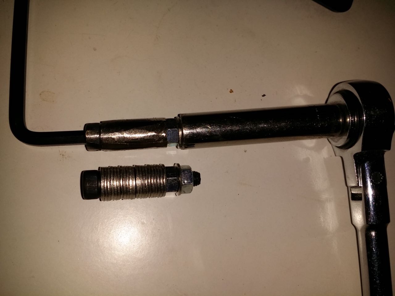
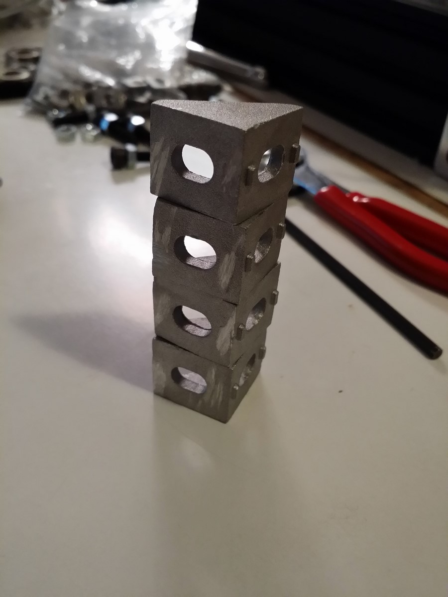
IF YOU ARE MAKING YOUR OWN WASHERS FROM COBBLEBOT AND LOCALLY BOUGHT WASHERS:
Take an M5x30mm socket cap head bolt and stack 21 of the CB 5x10x1.0mm washers
on it, all with the stamp lip facing the same direction so they stack and
center nicely. Screw a regular full size M5 nut (not a nylock nut) tightly onto
it, followed by one more CB washer and tighten on two more M5 nuts. Repeat this
so you have two sets of 21 washers ready to grind. Grind them down evenly so
they are less than 8.04mm around their complete circumference. You will damage
the bolt head and the innermost nut in the process, and they might not be
usable later.
· If
you're using a bench grinder, it'll take a long time unless your grinder is
strong enough to maintain speed under moderate force. Use a hex key and a deep
socket to grasp the roll of washers firmly while grinding. You might nick your
tools up a bit, be warned.
http://www.neveroddoreven.com/cobblebot/20150812_194923.jpg
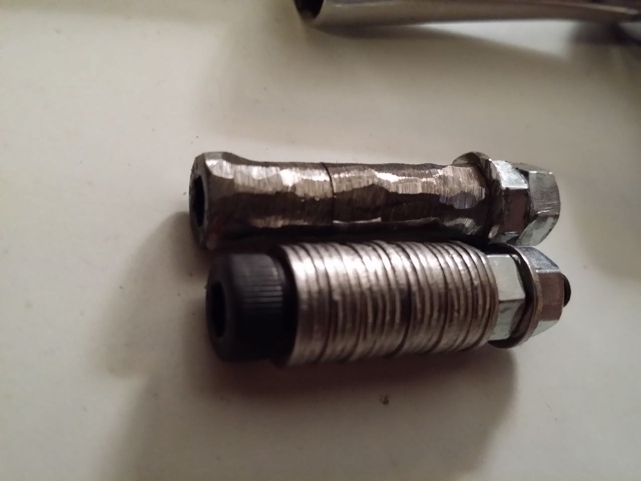
· If you're using an angle grinder, set the outer M5 nut standing straight up in a bench vise and slowly work the angle grinder up and down the roll of washers with the disc at a 20 degree angle so it doesn't catch easily between washers. Be careful that you don't grind all the way down to the bolt, it's easy to get carried away on one side.
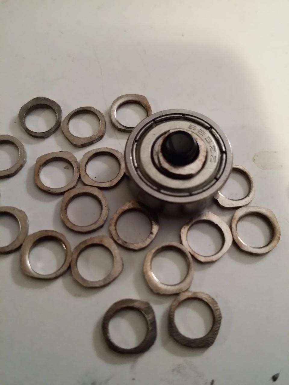
· Do your
best to evenly grind on all sides. You can see in the image link that mine
turned out lopsided, and I have to fix some of them or throw them out. A really
thin side is fine if it's small, it's not going to break anything.
http://www.neveroddoreven.com/cobblebot/20150812_201431.jpg
http://www.neveroddoreven.com/cobblebot/20150812_201820.jpg
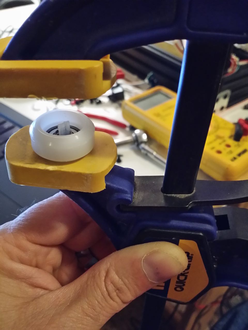
Press one 625 bearing into one side of a wheel using a bar clamp or C-clamp
with rubber jaw faces, and lay it bearing-down in the lower jaw of your open
clamp. Drop two of the Traxxas 5x8x0.5 washers down inside the center of the
wheel (or if you are using precision 5x8x1.0mm washers, just use one washer).
Align a second bearing on top of the wheel, drop the top jaw of the clamp down,
and slowly press the bearing in firmly. If the bearing starts to go crooked,
start over and reposition it. Repeat for the other 27 wheels. Do this even for
ugly wheels, you'll find out later if the issues are purely cosmetic. If you
have a drill press, you could probably use that to drive the bearings into the
wheels using some other method. Using pliers or vice grips in this step is
risky because a slip-up could crack/dent your wheel or punch into your bearing
seal. You now have 28 assembled wheels.
http://www.neveroddoreven.com/cobblebot/20150812_212224.jpg
(ignore the piece of nylon zip-tie centering the washer, I found it wasn't
needed)
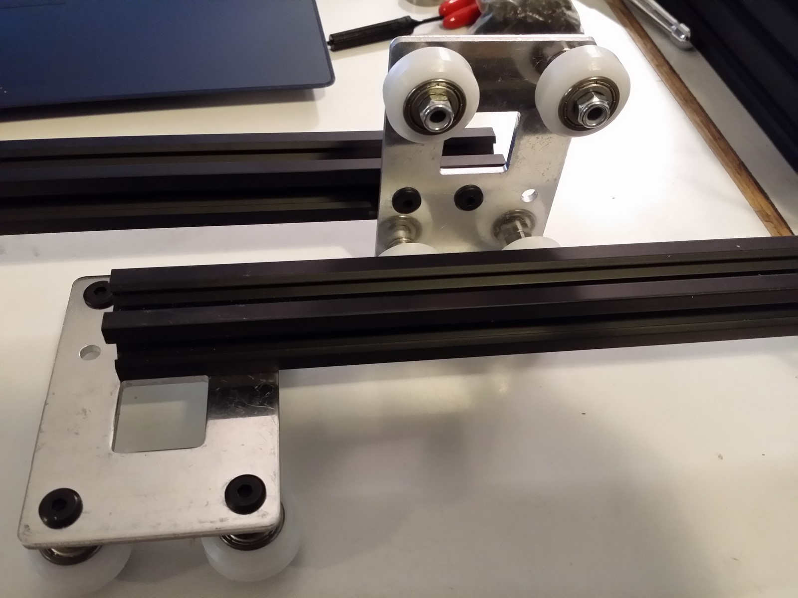
On a stable work surface that does not bump easily, assemble the wheel trucks
in the order that follows, substituting some (but not all) of the stock
Cobblebot washers. With the wheel plate's rough stamp edge facing down (or on
the Y carrier, with the routed-out hotend recess facing UP), drop four M5x25mm
bolts down into the holes closest to the corners for each wheel plate (1A kits
don't seem to have a stamp edge on the plates). Place a credit card on top of
the bolts, flip the plate over, and slide the plates from the credit card onto
your work surface with bolts sticking up.
If you are using wheels of varied cosmetic condition, sort them into a pile of
your 16 best wheels (Z plates), your four worst wheels (Y plate), and the rest
of them (X plates). Arrange all the plates out in a row with the wider holed
(eccentric) sides nearest you. Go down the two row of bolts with each of these
items in an assembly line to save time. Do all the eccentric spacers first,
then do the aluminum spacer ones. Nylock nuts should only be turned finger
tight at this time. If you are using the doubled-up Traxxas washers, you will
need to tap each wheel on its side and then align its internal washers using a
zip tie or paper clip before dropping it onto the bolt.
· For the
wide-holed bolts taking an eccentric spacer (fourteen of these):
Bolt head, plate, eccentric spacer (neck down), 2x fiber washer or 1x metal
washer of 5x8mm size, assembled wheel, nylock nut with nylon facing away from
bolt head.
· For the
narrow-holed bolts taking an aluminum concentric (regular) spacer (fourteen of
these too):
Bolt head, plate, larger 5x10x1.0mm CB washer with stamp edge facing away from
plate, aluminum spacer, assembled wheel, nylock nut with nylon facing away from
bolt head.
After all the wheel trucks are assembled (4x Z, 2x X, 1x Y), begin tightening
the nylon lock nuts holding on the eccentric spacers until the spacers fully
seat into the plates, then re-loosen the nuts. Turn all of the eccentric
spacers so its narrowest side (bearing a shallow factory groove mark) faces
outside and away from the next closest wheel with the aluminum spacer. This
ensures the wheel truck begins life at its loosest setting.
http://www.neveroddoreven.com/cobblebot/20150814_193729.jpg
For all four wheels on each of the wheel trucks, turn each nylon lock nut until
you feel the bearing no longer spins very freely on its own, and then tighten
it slighty again and again until you notice the bearing becomes stiff and
begins to demonstrate a "crunchy" feeling when you turn it. If you
are able to tighten firmly without any crunchy feeling, then just leave it
fairly tight and move onto the next wheel. Otherwise, turn the bearing back and
forth at least ten times rapidly. On some bearings you will feel that some or
all of the crunchy feeling begins to go away -- you should very slightly
re-tighten it one or two more times until the crunchy feeling starts to return.
After the crunchy feeling is persistent even with rapid turning, loosen the
nylock nut just slightly and try rotating the bearing again a few times. Keep
loosening slightly until the bearing is a little stiff, but does not
demonstrate significant crunchiness. If a wheel still ends up crunchy after all
this,, start over with it and spin it around a lot more to exercise the bearing
before finally giving up and leaving it in a barely tightened crunchy state.
You do not want to aim for a really smooth free-spinning bearing experience --
it's not necessary for accurate prints, and with the supplied bearings, loose
nuts will invite slop in your gantry later that you'll probably never be able
to chase down. The wheels should rotate with effort, but not freely on their
own, and there should not be any significant crunch or catch during rotation.
NOTE: if you grind your own 5x8x1.0 washers from the CB supplied or locally
bought ones, you may notice crunchiness and catching before the nylon lock nut
is hardly tightened at all. This is probably one of your homebrewed washers
being lopsided or having a sharp spur, and you'll need to retrieve and fix it.
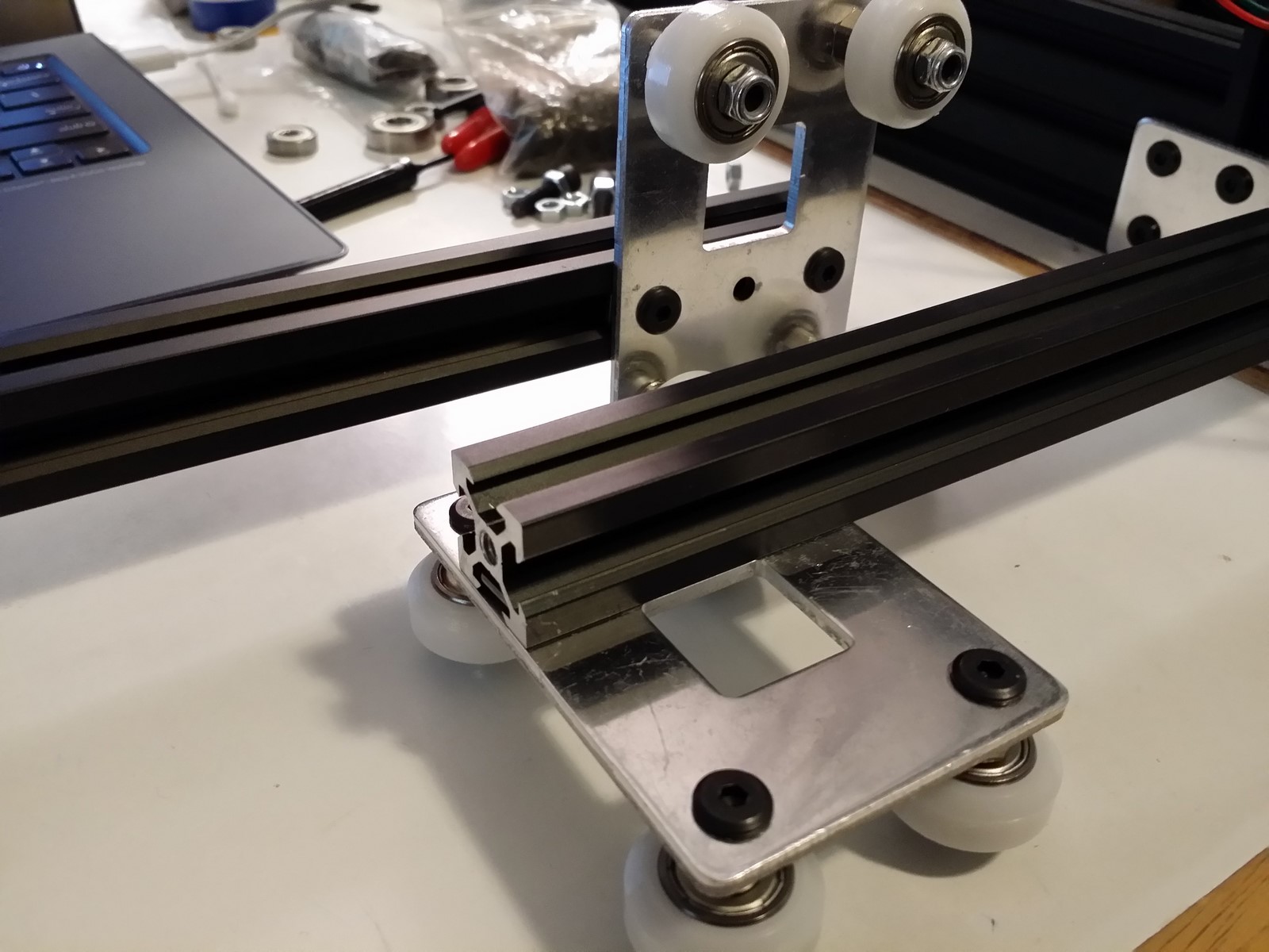
Take one of the 20x60 rails out. For each of the wheel trucks, temporarily
slide the truck onto the 20x60 rail and run it back and forth. You should feel
it running somewhat smoothly (do not tighten any trucks at this time, even if
they are very loose on the rail). Don't worry about minor clicks and catches
that occur once per rotation on the wheels, they won't show up in the prints
for long (if ever) and should wear off or smash down after maybe 20 hours of
printing. Take a look at this informational video for more evidence. https://youtu.be/9jPSkIKm2JE
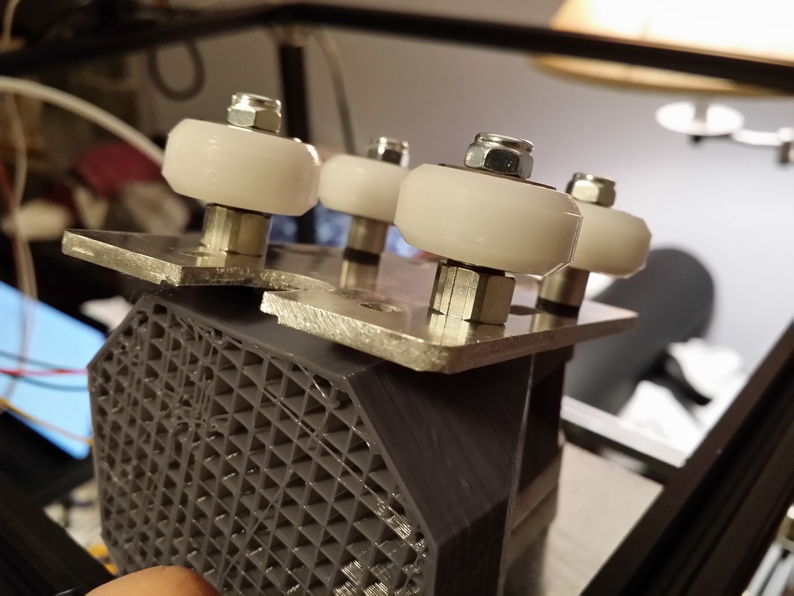
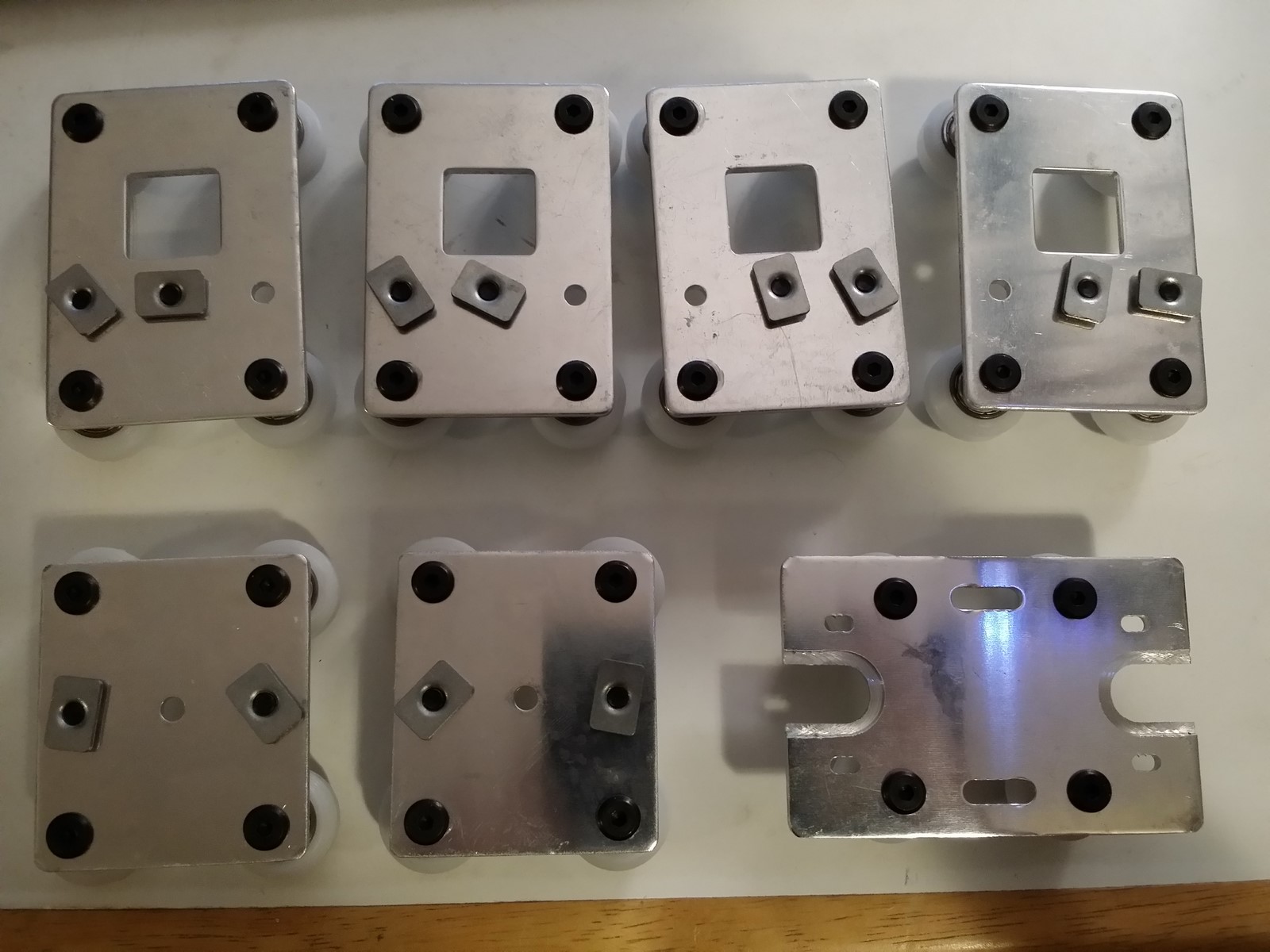
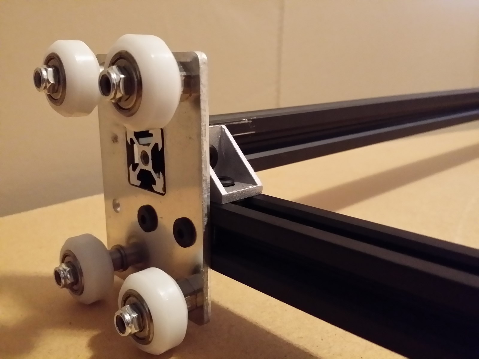
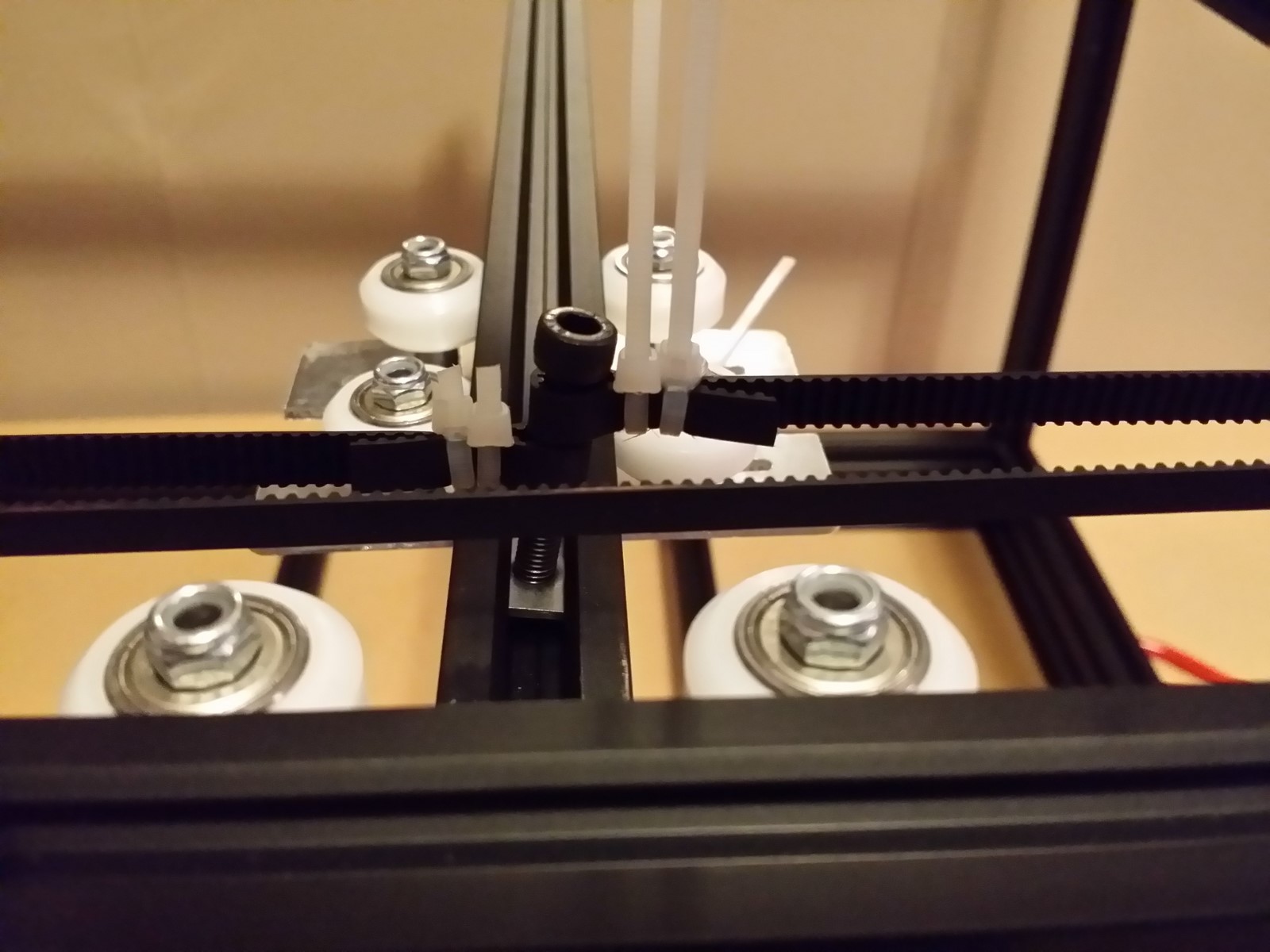
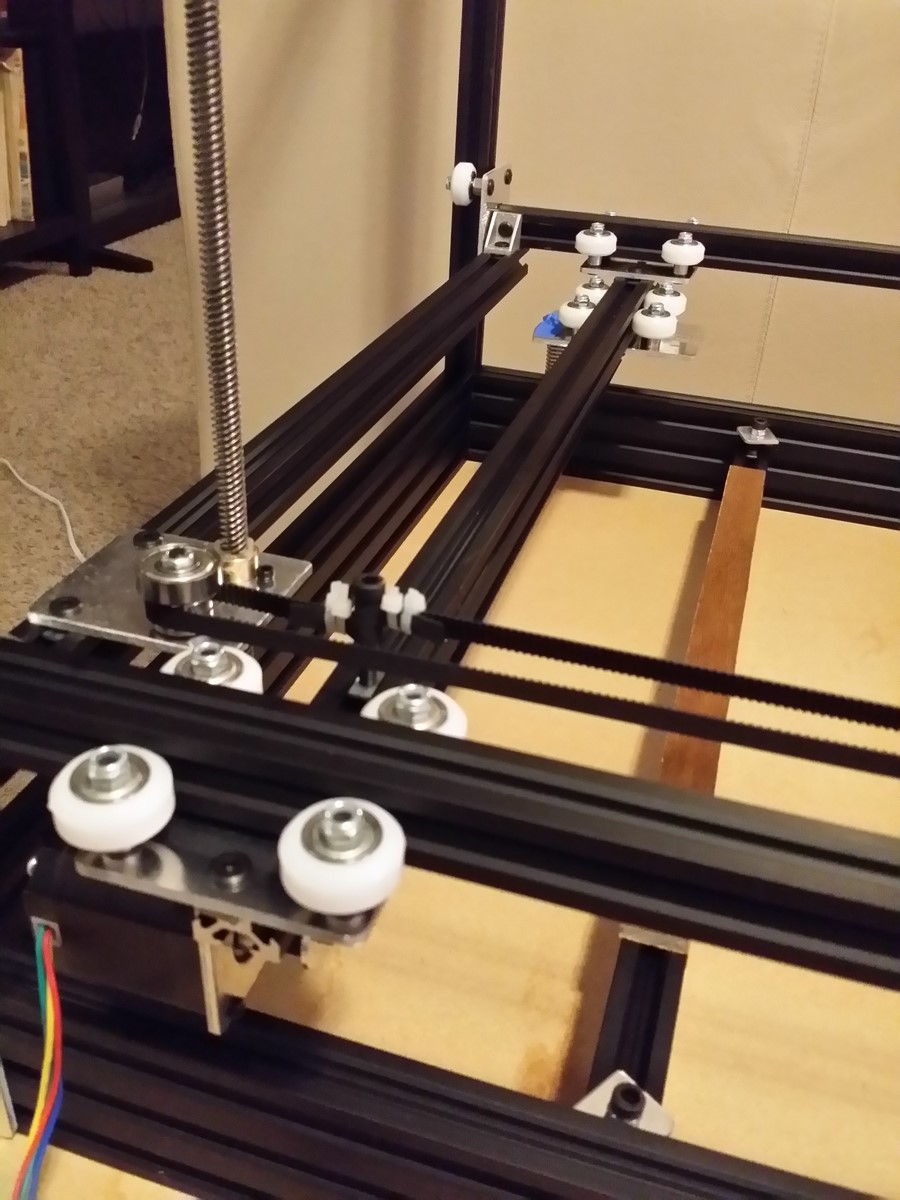
Now it's time to add the M5 T-nuts and 8mm screws to the X and Z plates. Refer
to the Cobblebot instructions and diagrams in part 2, taking care to add the
fasteners in the right places per your 1A or 1B kit requirements. Here is a
photo of a 1A assembly; a 1B assembly would instead have the T-nuts/screws on
the outside holes of all four Z plates.
http://www.neveroddoreven.com/cobblebot/20150815_074736.jpg
Re: Building a working Cobblebot gantry
Posted: Sat Aug 15, 2015 2:19 pm
by neveroddoreven
Part 3A: Base frame assembly
Set out the exact number of parts below. Refer to the Cobblebot manual for
parts diagrams, but you will instead need:
· All four of your 20x60 rails
· Four of your longest 20x20 rails (560mm for 1A kits or 576 for 1B kits) (prefer perfect rails, or if you have none, rails with at least one perfect end)
· All eight base join plates
· 36x M5x8mm low profile bolts (the manual called for 40 of these)
· 36x M5 T-nuts (the manual called for 44 of these)
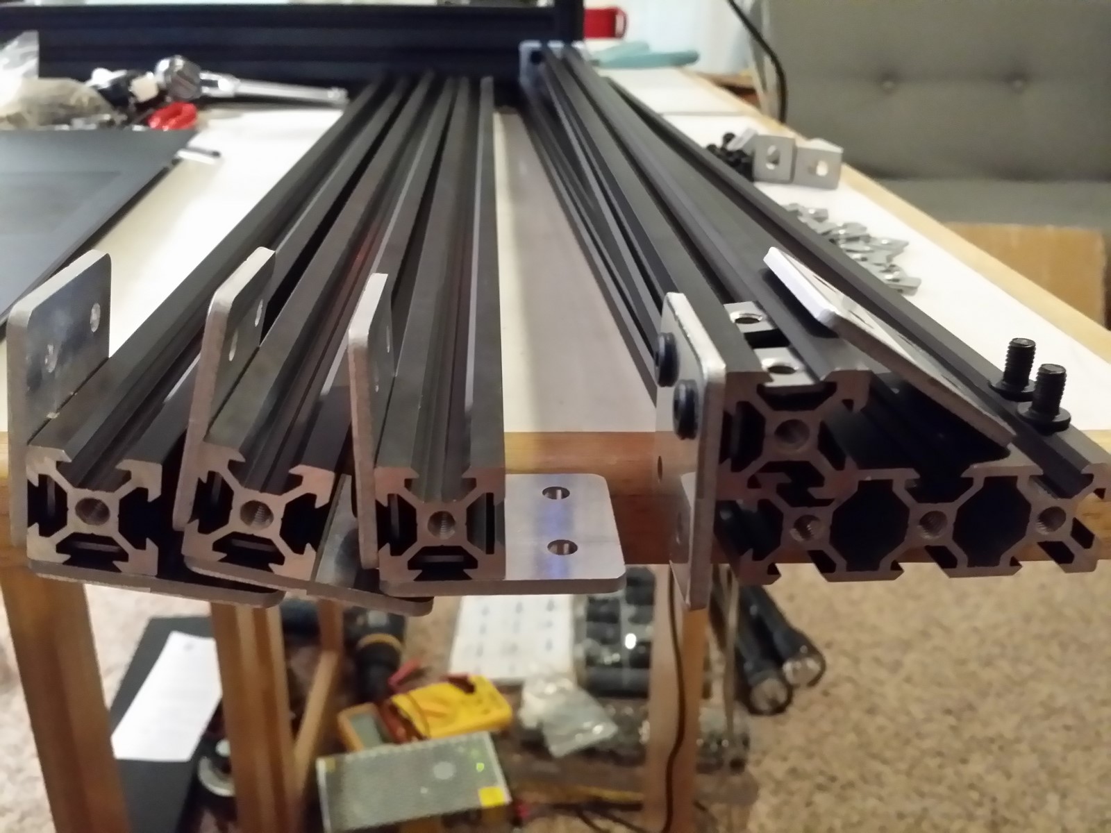
For convenience, set one of the 20x60 rails flat in a row on your work surface,
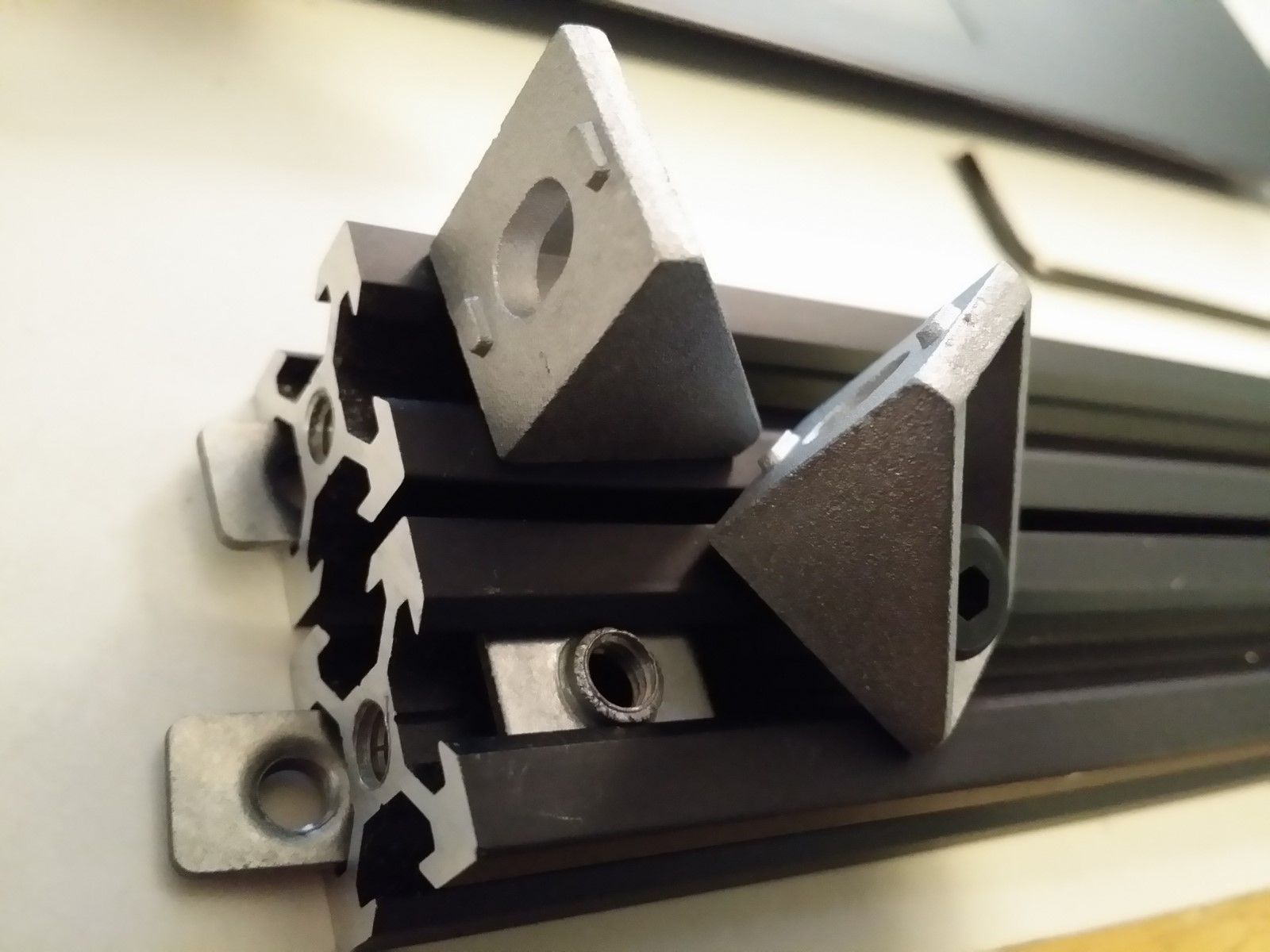
and lay a 20x20 rail flat on the 20x60. On the perfect end of the 20x20 rail,
slide two T-nuts in with the flatter side facing away from the rail. Place a
base join plate over the freshly installed T-nuts with the sharp edge against
the rail, and screw one side of the base plate down finger-tight using the
M5x8mm bolts. Don't worry about alignment for now.
· The four holes are not dead centered in the base join plates, which has no significance on printer function. But for an aesthetically pleasing base, you will want to identify the wider side of the plate that also has its holes set furthest away, and align that side with the end of the 20x20 rail. If you don't care, then use the plate in any orientation you like. Make up your mind now -- you can't reassemble this part later without throwing the printer out of whack.
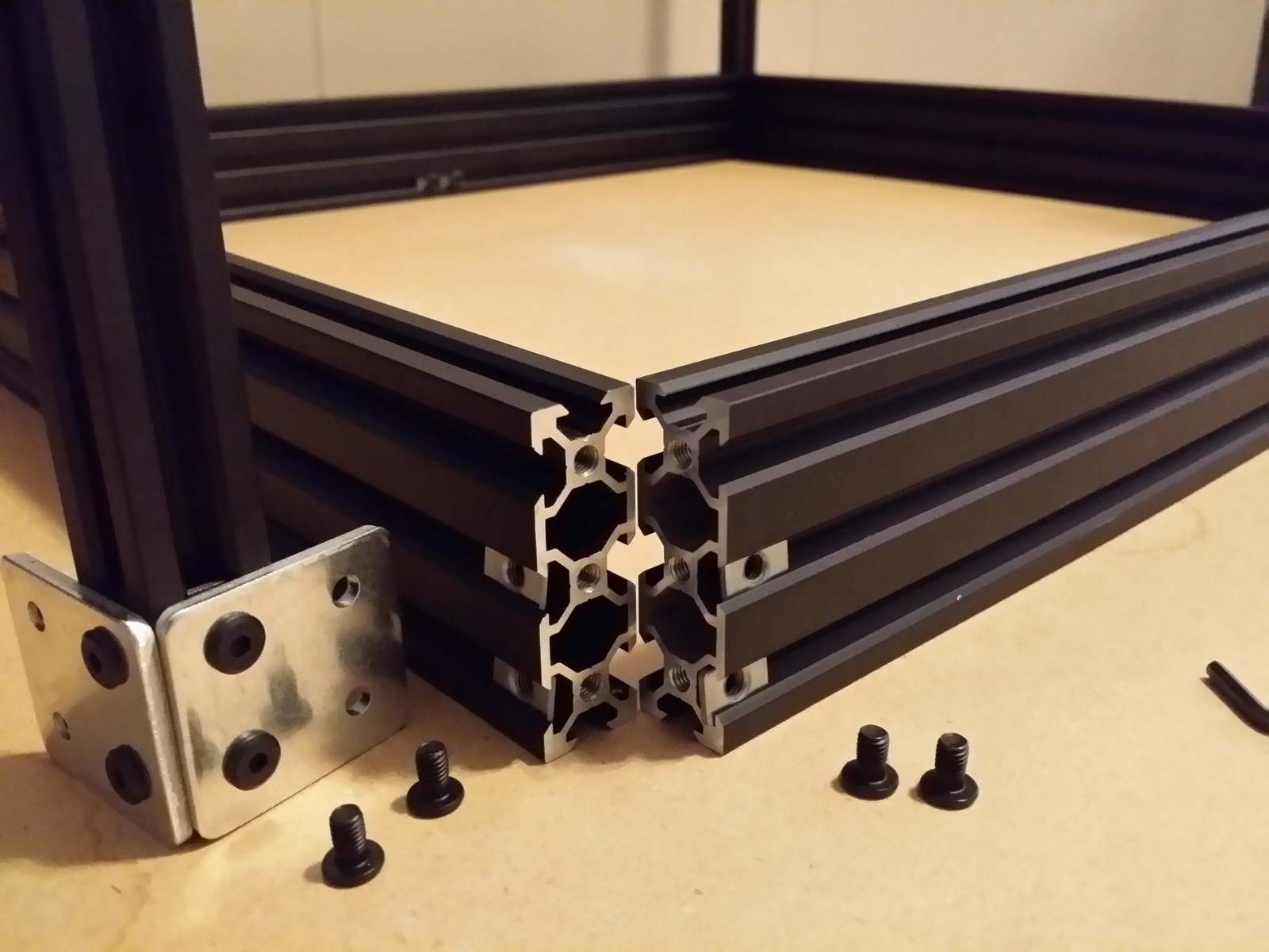
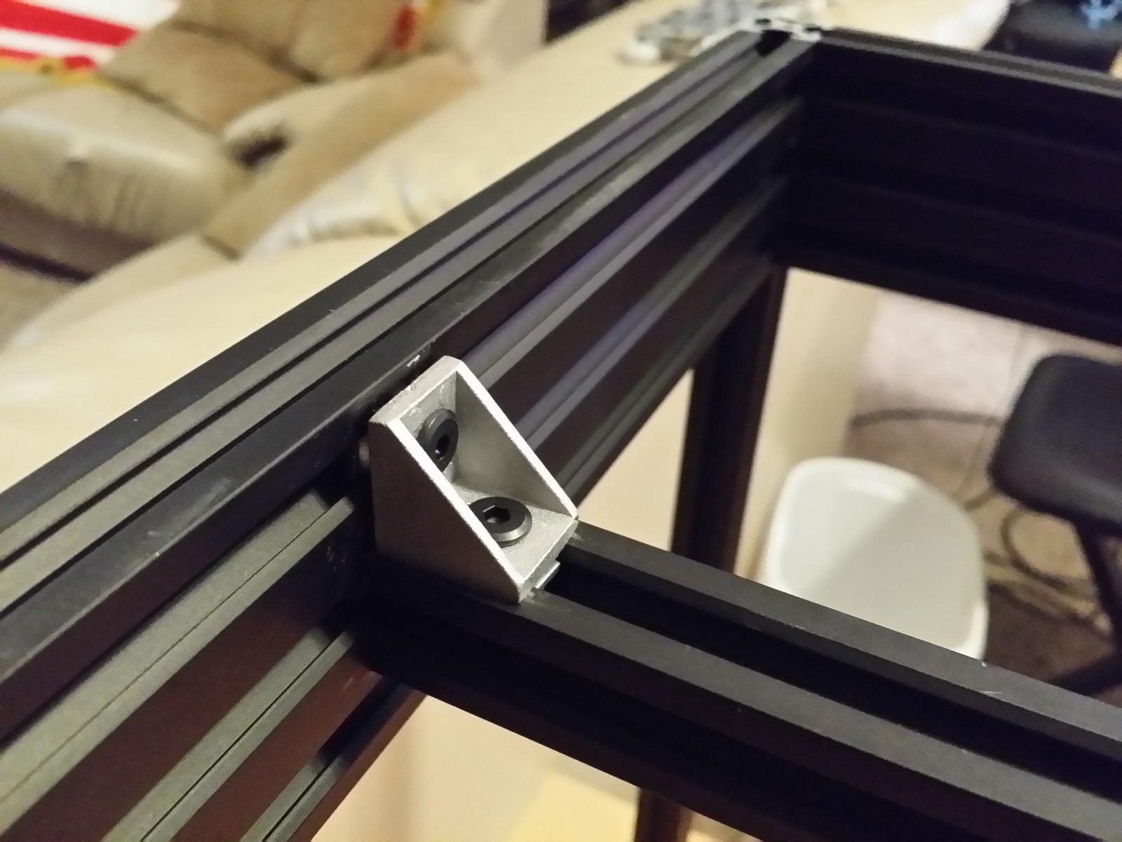
Rotate the rail 90 degrees so that the installed base plate is pointing
down toward the work surface, and install another base plate in the same
manner, but with the new plate shifted so that the two base plates form an L
when viewing the end of the rail. Repeat with the other three 20x20 rails http://www.neveroddoreven.com/cobblebot/20150815_093233.jpg
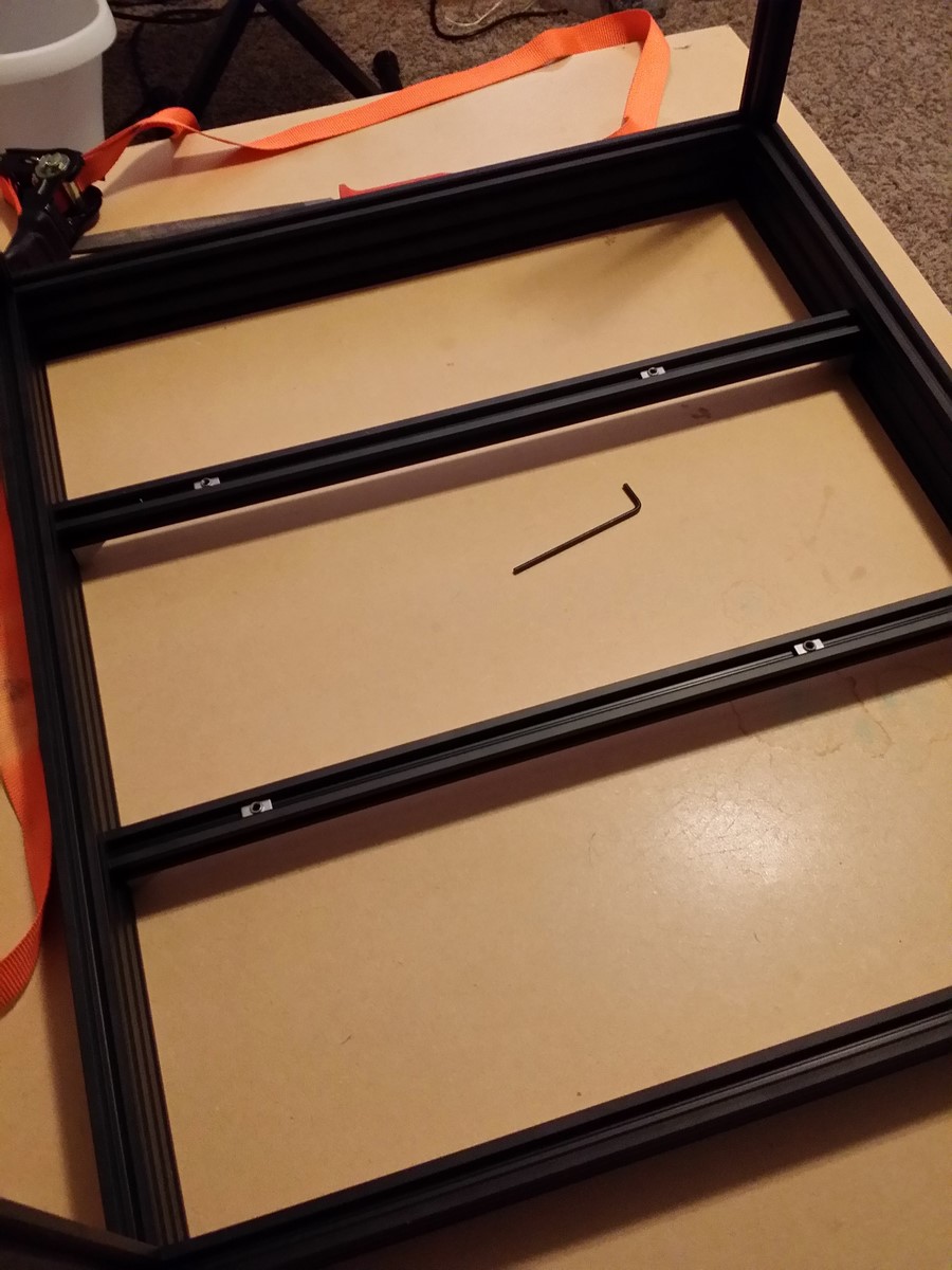
On a hard work surface that is reasonably flat and free of fibers and debris,
set down the four 20x60 rails in a box formation standing up with their 20mm
wide face. If you have 20x60 rails with end dents sticking out beyond the end
of the rail, use a hand file to manually take the dented material down just
enough so they do not violate the otherwise factory-cut flatness of the rail's
end. Do not attempt to reform or hammer down the dented metal, or you might
warp your rail. If you have end dents that only stick up along one wide face of
the rail, orient those dents to harmlessly face inside the box. If you have end
dents sticking out on both wide sides, gently file enough of them down until
one side is flat with no dents. Dents or scrapes anywhere else along the rail
are harmless.
In each of the longer 560mm 20x60 rails, slide two M5 T-nuts into the bottom
slot on the inside of the box with the flatter side of the T-nut facing inside
the rail, move them to the middle of the rail, and put M5x8 bolts into them
finger-tight so they stay put. You will later mount your build plate rails on
these four bolts.
On the outside face of each of the 20x60 rails, insert one T-nut flat-side-out
into the bottom slot, and another T-nut flat-side-out in the middle slot, on
both ends of the rail (four total nuts added per rail in this step). The
Cobblebot instructions suggest to also:
· slide two T-nuts into the outside-facing top slot of just one long rail to mount your LCD, and
· slide two T-nuts into the top-facing slot of each of the shorter rails.
However, you don't need to do these two bullets above, as we will
instead top-mount the Z-motors, and mount the LCD plate to the top of the
printer together with all the other electronics except the power supply.
On each corner of the box you've arranged, stand up one of the 20x20 rails with
the base plate holes aligned over the T-nuts in the ends of each 20x60 rail,
and fasten two M5x8 bolts finger-tight through each base plates into the
20x60-mounted T-nuts. You should now have something resembling an upside down
table frame. Don't move the frame around much at this time, it's likely to come
apart somewhere.
http://www.neveroddoreven.com/cobblebot/20150815_110855.jpg
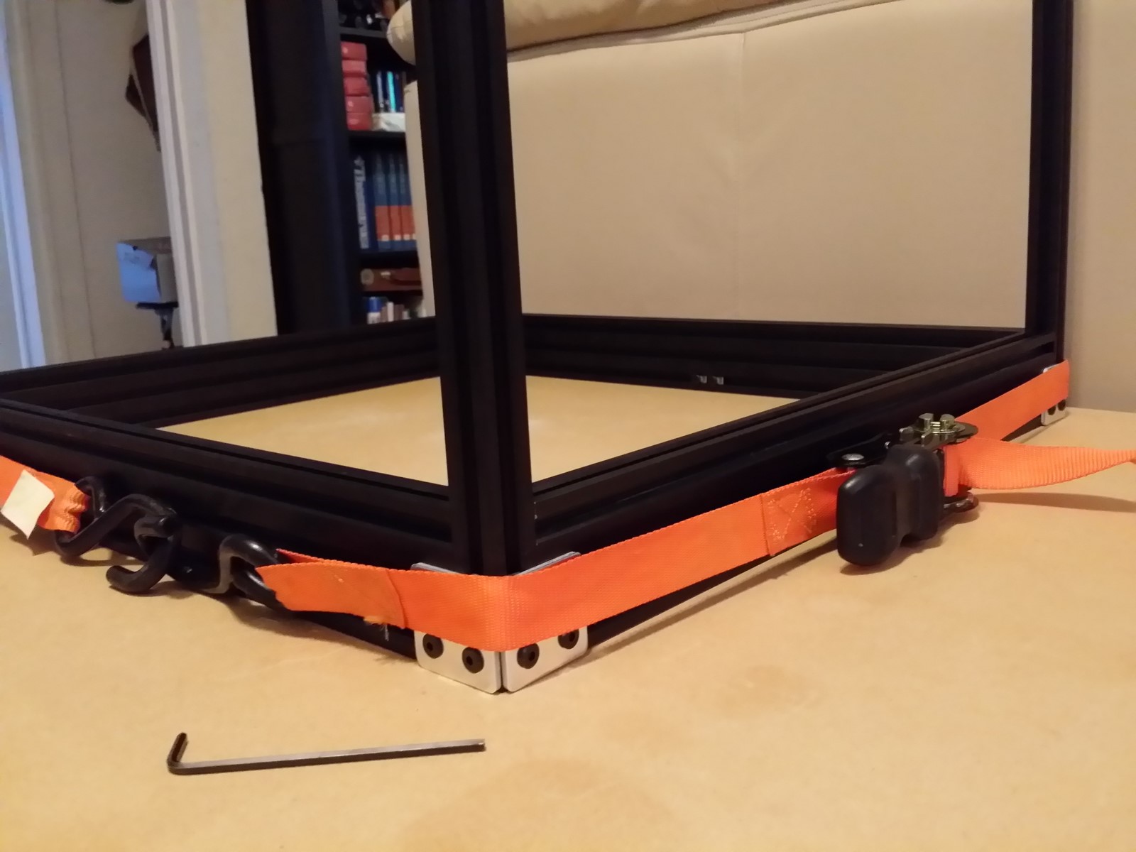
Take your ratcheting tie-down strap, wrap it around the base, and ratchet out
enough of the slack strap so you can position the strap over the middle of the
20x60 slots with the bottom sets of screws exposed for fastening. Ratchet it
down fairly tight, and try to slightly move around each of the 20x20 rails
sticking up -- you should be able to work it back to the tightest position against
the 20x60 rails, with the bottom ends of the 20x20 rails flush or very slightly
above flush with the bottom faces of the 20x60 rails.
http://www.neveroddoreven.com/cobblebot/20150815_111547.jpg
Turn the frame over and gently set onto its "legs", then use a mallet
or the soft handle end of a hammer or file to gently tap and align the pieces.
Align the base plates so they are straight and tap them down until they don't
stick out past the bottom of the 20x60 rails. Tap the 20x60 rails up or down
until they are flush with each other and with the 20x20 rail ends. Once
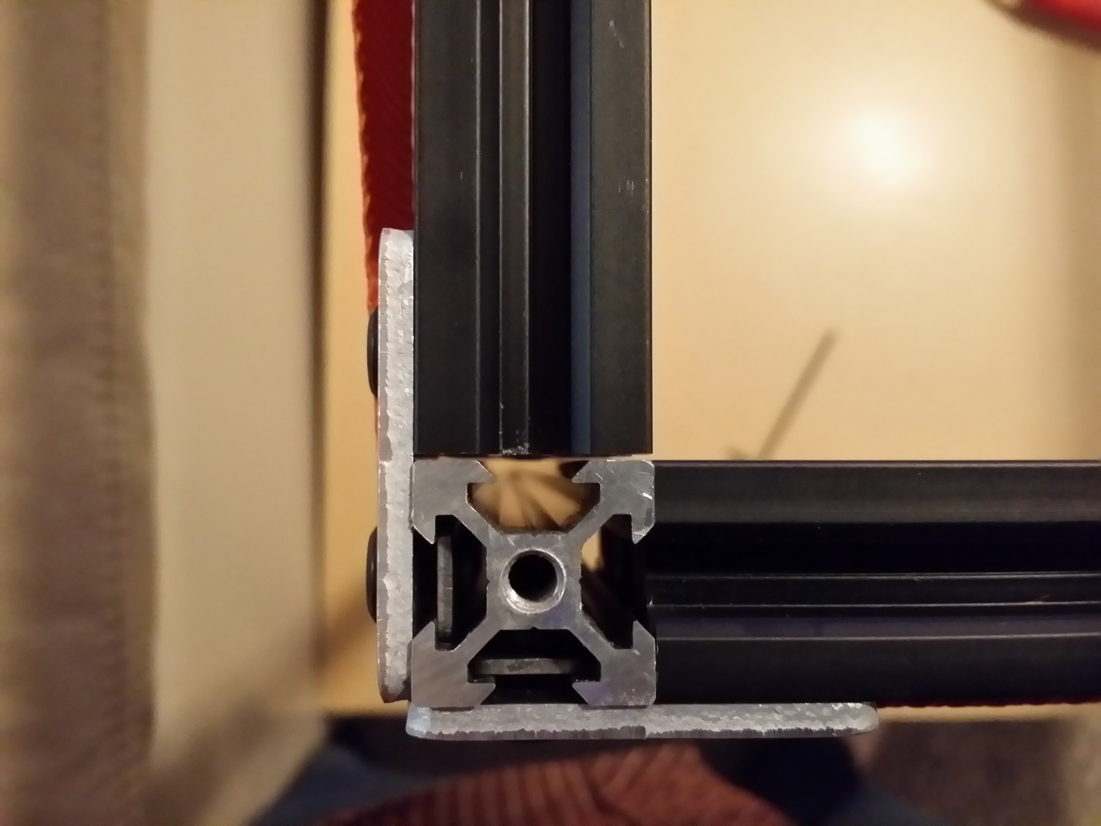
aligned, double-check all four corners for alignment again. Set up a light
background (piece of paper) underneath each leg on your work surface, ensure
your workspace is well-lit, and hover slowly over each of the corners. If you
see any slice of light peeking through inside the corner joins, work it around
until the rails butt firmly against one another AND the 20x60 rail corners are
just about touching against each other (and then realign the rails so they are
flush again). This is going to be the bottom face of your printer, and if you
don't add adhesive feet later, any corners sticking out will scratch and grind on
your work surface as the printer does its thing.
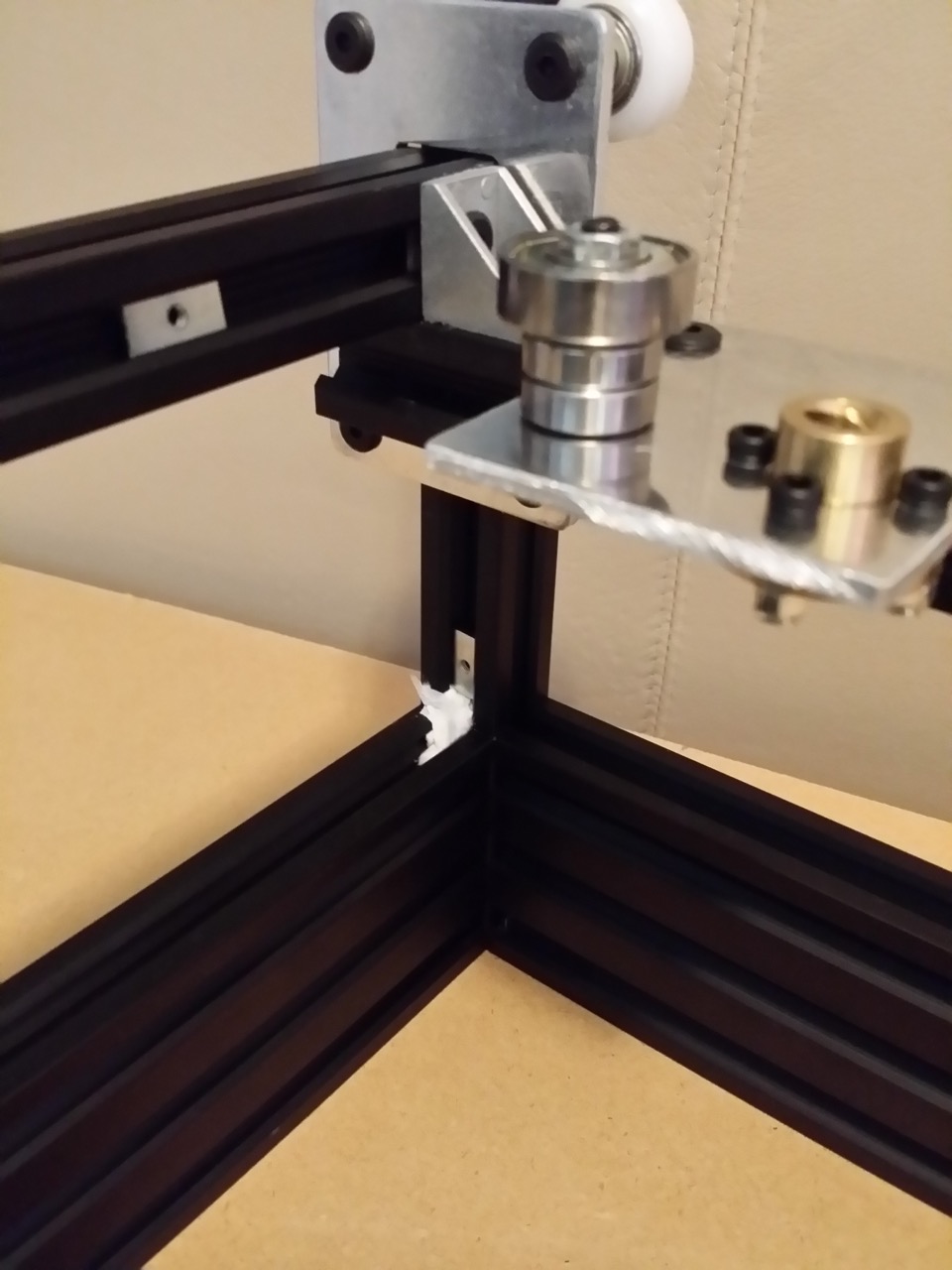
http://www.neveroddoreven.com/cobblebot/20150815_114038.jpg
(you can see there is a gap here that needs to be fixed - those 20x60 rails
should almost be touching at the corner!)
Now ratchet strap down to a really tight hold, and tightly screw in the eight
bottom slot M5 bolts all the way around the frame. By tight, I mean turn it
tightly until the bolt stops, and then try for a second tightening -- on the
second try, a 90mm long 3mm allen key should flex about 15mm further after
having driven the bolt in tight. Loosen the ratchet strap, move it down the
20x20 rails just enough to uncover the remaining eight M5 bolts, and re-tighten
the strap down firmly. Double check from overhead that your corners are still
tightly aligned and the rails are still butting against each other. Tighten the
remaining M5 bolts all the way around and then remove the strap. Flip your
now-solid base over and inspect all joins and corners for flushness.
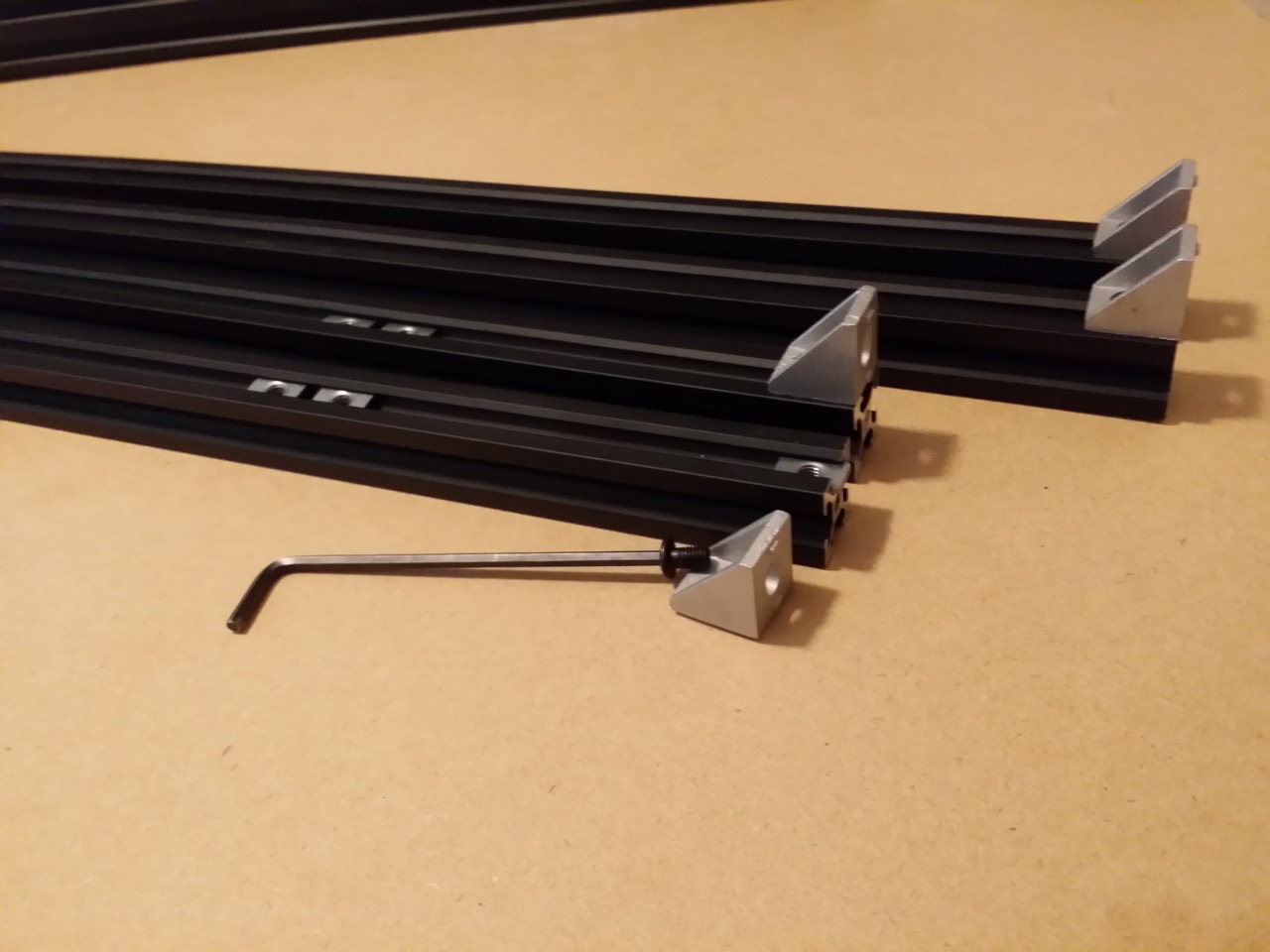
Part 3B: Build Plate rails
You will need:
· 2x 500mm length 20x20 rails
· 4x 90 degree corner brackets (the manual accounted for 4x of these in Part 3 but uses 8x -- we saved four brackets)
· 4x M5x8mm low profile bolts (the manual accounted for 4x of these in Part 3 but uses 12x -- we saved eight M5x8mm nuts)
· 8x M5 T-nuts (the manual accounted for 8x of these in Part 3 but uses 12x -- we saved four T-nuts)
Insert one T-nut in the end of one of the rails, with the flatter side of the
nut facing the rail. Place a corner bracket over the nut with the 90 degree
face aligned on the end of the rail, and screw it down lightly with an M5 bolt.
Slide the fastened bracket away from the rail's end by about 5mm. On the
opposite face of the rail (top vs bottom), insert a T-nut with the flatter side
of the nut facing the rail. Repeat these steps on the other end of the same
rail, with the brackets mounted on the same rail face. You now have a build
plate rail; now assemble the other rail in the same way.
http://www.neveroddoreven.com/cobblebot/20150815_123931.jpg
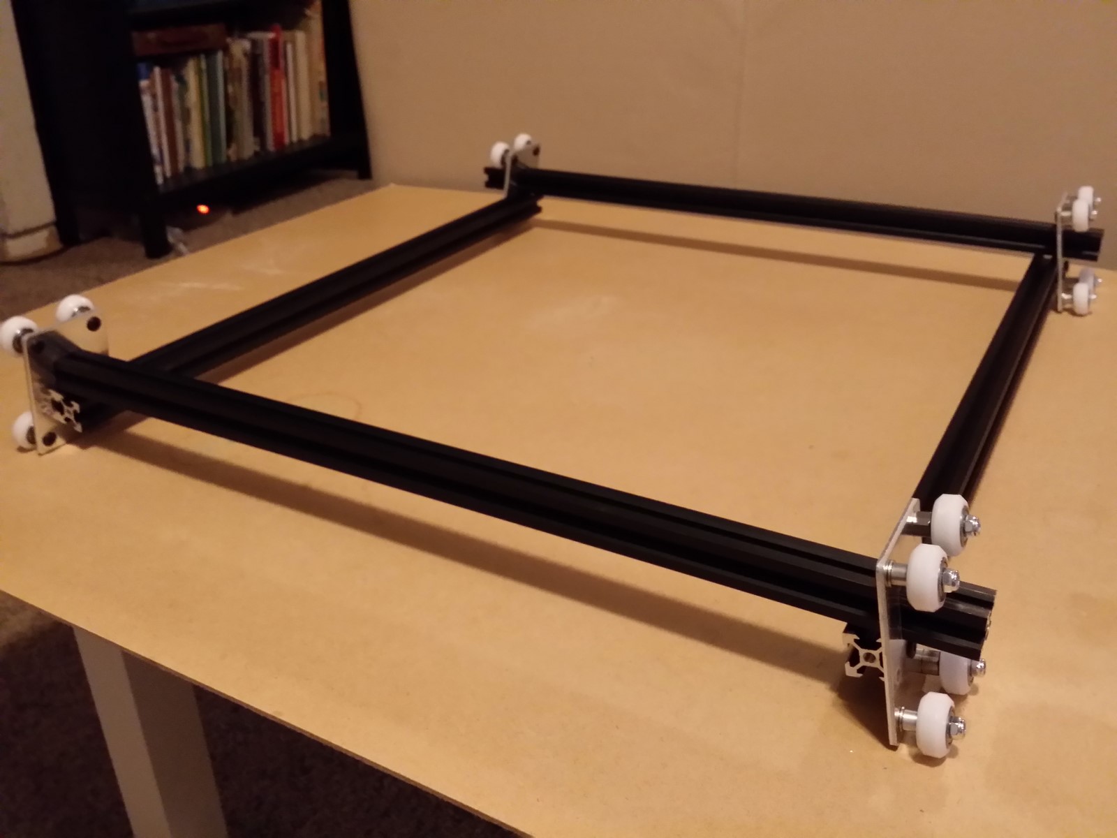
Turn the frame over onto its legs with the bed base facing up, and remove the
four standalone M5x8mm bolts you mounted earlier on the base interior. Space
the T-nuts along the rail so they split the printer base area into roughly
one-third sections, and are aligned with their complementary T-nuts on the
opposite side of the base. The spacing ratio is not critical and will be
adjusted later. Take one of the build plate rails and gently position between
two of the T-nuts that face each other, with the rail hanging down, and slide
the corner bracket up against the 20x60 base rail on one side. Fasten the
corner bracket slightly more than finger-tight against the base, and then
fasten the other side the same way. Fasten the other rail in the same manner.
You will almost certainly scratch up your base rail with corner bracket aluminum
marks -- this is unavoidable in the long run so don't worry about it.
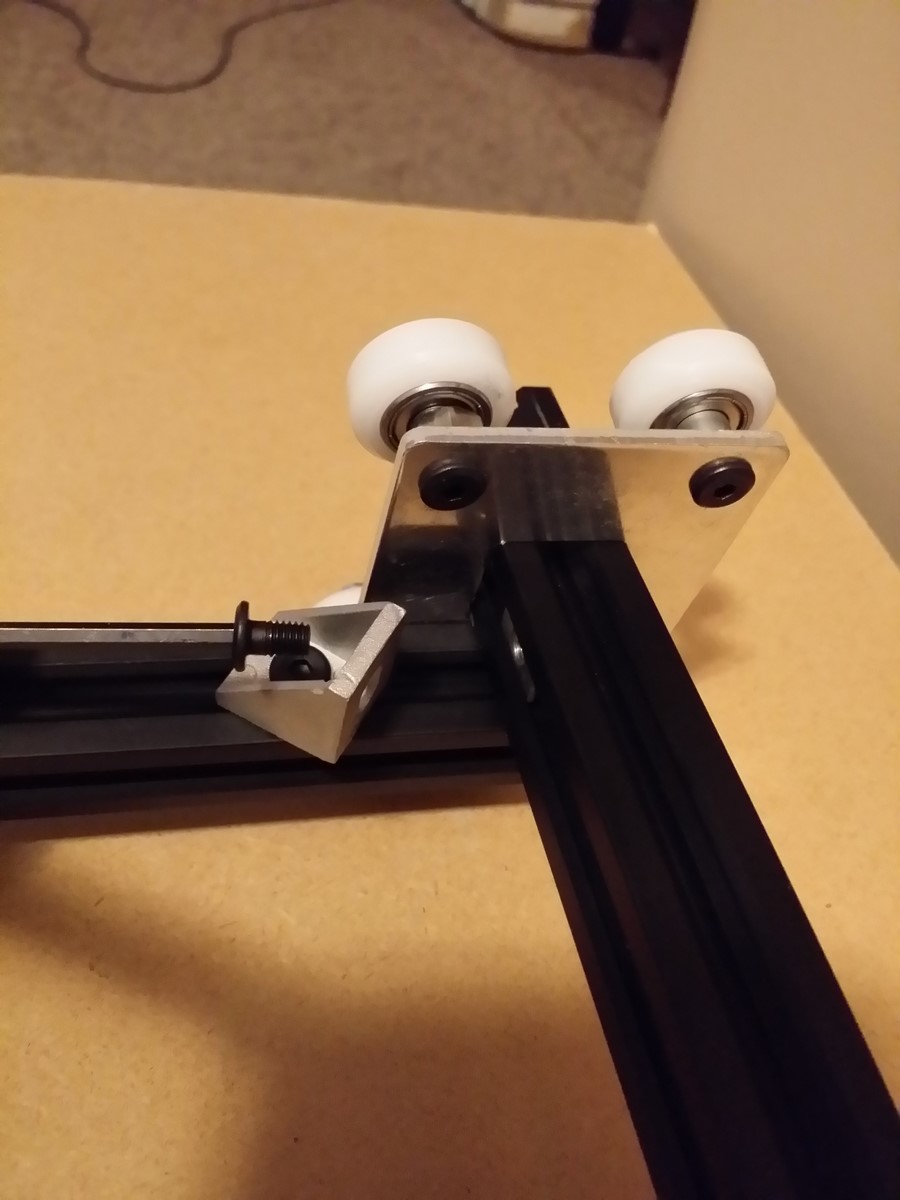
IMPORTANT: Although it is tempting to trim off the tabs sticking out of the
corner brackets that butt up against the base, don't do so here, as they are
useful in creating a smaller surface area that is both easy to reposition and
also tightens well against the base for build plate alignment purposes.
http://www.neveroddoreven.com/cobblebot/20150815_133239.jpg
http://www.neveroddoreven.com/cobblebot/20150815_133310.jpg
Re: Building a working Cobblebot gantry
Posted: Sat Aug 15, 2015 2:19 pm
by neveroddoreven
Part 4: Gantry Cage Assembly
You will need:
· 8xx M5x8mm low profile screws (the manual calls for 12x)
· 13x M5 T-nuts (the manual calls for 21x but many of these are already mounted to the plates)
· 1x M3 T-nut (the manual calls for two)
· 4x 90 degree corner brackets
· 1x M5x30mm socket cap head screw (you can use the 25mm one from CB but 30mm is better for the X belt motor/idler alignment)
· 1x 45-inch GT2 timing belts
· All your assembled wheel trucks
· 2x 551.5mm rails
· 1x 560mm rail and 2x 540mm rail (1A kit), or 3x 576mm rails (1B kit)
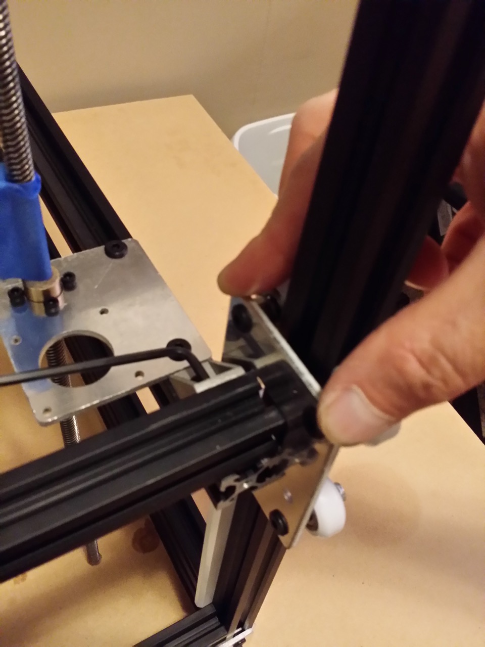
Take your two shortest rails (1A kit 540mm) or two longest rails (1B kit 576mm)
and lay them on a hard work surface. Slide the two T-nuts sticking out of your
four Z wheel trucks (the ones with the big square holes in them) into either
end of the rails, on the same face and oriented in the same direction. Fasten
the trucks to the rails loosely.
· For 1A
kits, match the appropriate fastener-ready Z truck to each rail end so that the
truck's square hole aligns with the end of the rail, and you end up with a
section of the Z plate with an empty plate hole and no rail.
http://www.neveroddoreven.com/cobblebot/20150815_165250.jpg
· For 1B
kits, your plates are all the same and you will align the edge of the rail with
the edge of the plate.
http://www.neveroddoreven.com/cobblebot/20150815_165347.jpg
Slide each of the Z rail wheel trucks down onto the build frame
and guide it to the base of the frame. Don't worry about any wheels being loose
on the rail. Ensure the rail is evenly aligned with the truck plates at both
ends. Apply pressure to the Z wheel truck so that the wheels with the aluminum
spacers are touching against the rail, and then fasten the available plate
screw(s) into the rail nuts tightly. If you have a 1A kit, remove the rail and
tighten the remaining nuts that were previously obscured. Remove the Z plate
rails from the base frame.
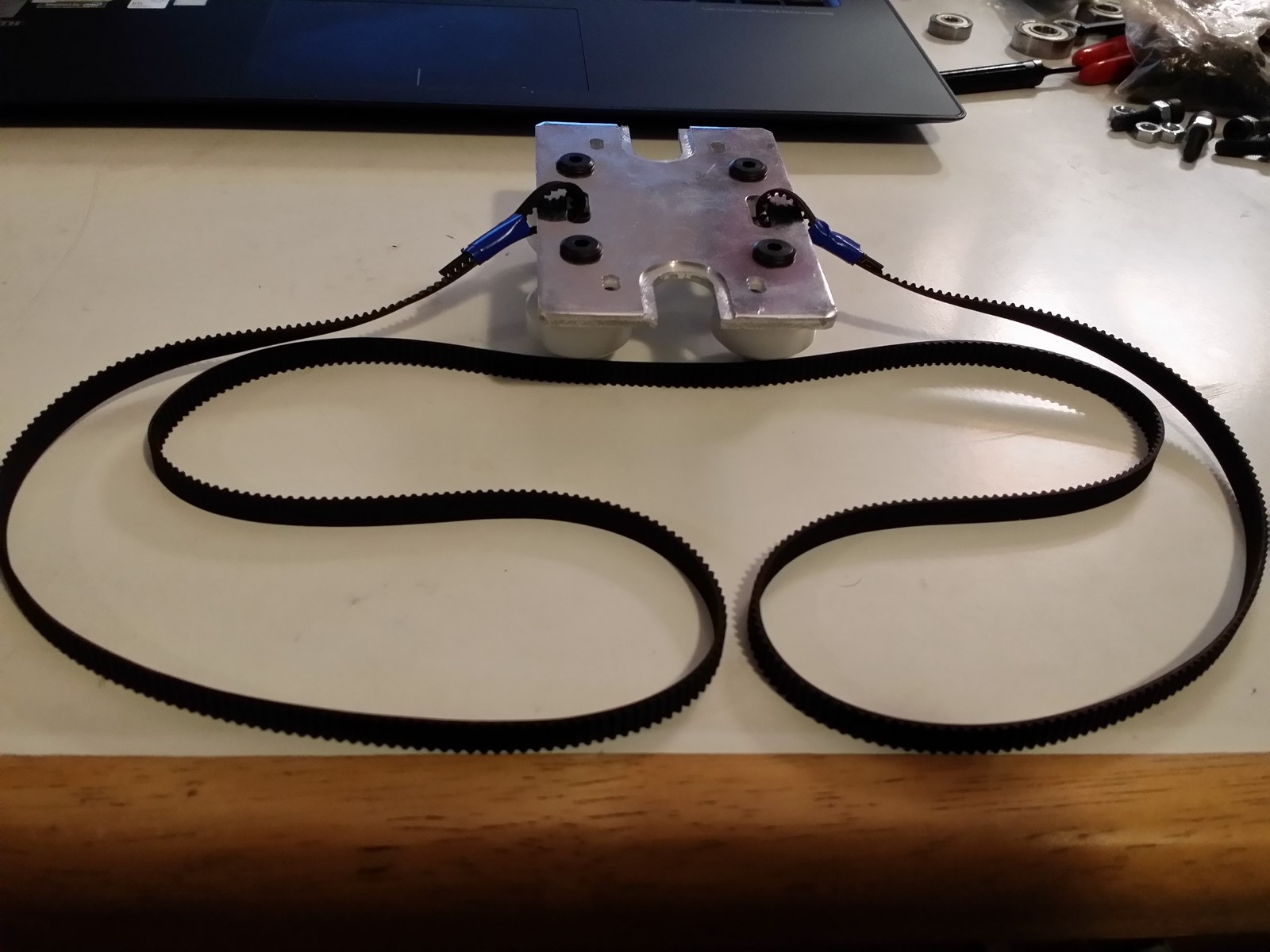
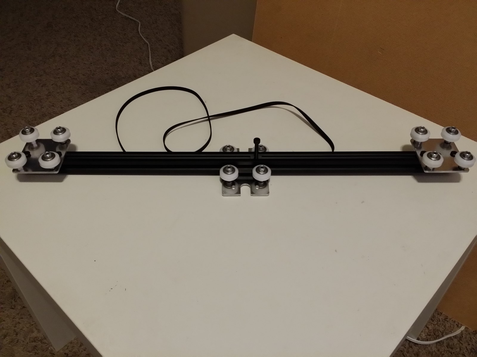
Prepare two pieces of electrical tape roughly 40mm long. Set your Y truck on
your work surface, wheels facing down and the C-shaped cutouts pointed toward
and away from you. Take the GT2 timing belt and lay the midsection of it
teeth-down on top of the Y truck. On both sides of the Y truck, arch the timing
belt back under itself with the teeth facing each other, and send the ends of
the belt up through the elongated slots on either side of the Y truck (the ends
of the belt should be facing teeth up as they pass through the Y truck). Pull
about 40mm of the timing belt through the slots, and fold it back over onto
itself with the teeth meshing together. Tightly wind the electrical tape around
the interlocked belt ends so it doesn't come loose during assembly. We will
remove the tape later. Pick up your Y truck, hold it facing wheels up, and
confirm your belt is hanging down from the Y truck in a flat loop without any
twists.
http://www.neveroddoreven.com/cobblebot/20150815_170643.jpg
Take the remaining longest rail that you set out for this step (560mm for 1A,
576 for 1B) )and slide your Y wheel truck onto it from underneath with the belt
tabs aligned along the rail and the belt loop hanging down freely. If there is
a dented area on just one side of the rail, point the dent toward the Y truck
plate. If there are two opposite sides dented, have the wheels gliding over the
cleanest two sides of the rail. (see the next image link for reference)
Slide the Y truck along the rail and find the loosest point along the wheels'
rotation, and stop there. Try to twist the Y truck on the rail and see which
elliptical/aluminum wheel pair is loose. Gently rotate the elliptical spacer so
the vertical groove starts to rotate in the direction of the corner it is
nearest to, until you feel it become a little more snug and the twisting free
play is gone from the truck. After tightening both elliptical spacers, send the
Y truck near one end of the rail, hold it firmly (this might hurt so maybe use
a work glove) and try torqueing it again with your hand on the other end of the
rail. Ensure there is no free play, without overtightening.
· NOTE: turning the elliptical spacers with the imprinted groove rotating toward the closest corner will ensure that all wheel adjustments are orbiting toward the outside of the truck, keeping it in balance and widening the wheelbase for more stability. The least ideal adjustment would be turning both elliptical spacers on a truck in the same (anti-)clockwise direction, which would introduce a slight shear force within the truck.
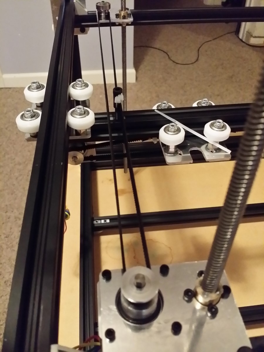
Set the Y truck plate/rail assembly on your work surface and center the Y truck
in the middle of the Y rail (the rail should be on top). Slide one M5 T-nut
(flat side away from the rail) into the rail's top slot, move it temporarily to
the middle of the rail (over the Y truck), and install an M5x30mm socket cap
head screw into it finger-tight (or use a CB-supplied M5x25 screw if you don't
have a 30mm one). On the same top slot, slide the X trucks on either end of the
Y rail using the preinstalled fasteners, align the plates with the rail ends,
and screw them on a little more than finger-tight for now.
http://www.neveroddoreven.com/cobblebot/20150815_181139.jpg
On the four 90 degree corner brackets, use a motorized spinning grinder of some
kind to grind off the protruding tabs on one face only. Do your best to
eliminate all traces of the tab, and also not to disturb the flat areas in the
four corners of the bracket face, because grinding the whole corner of a face
will throw its squareness out of alignment. Allow the brackets to cool.
http://www.neveroddoreven.com/cobblebot/20150815_182938.jpg
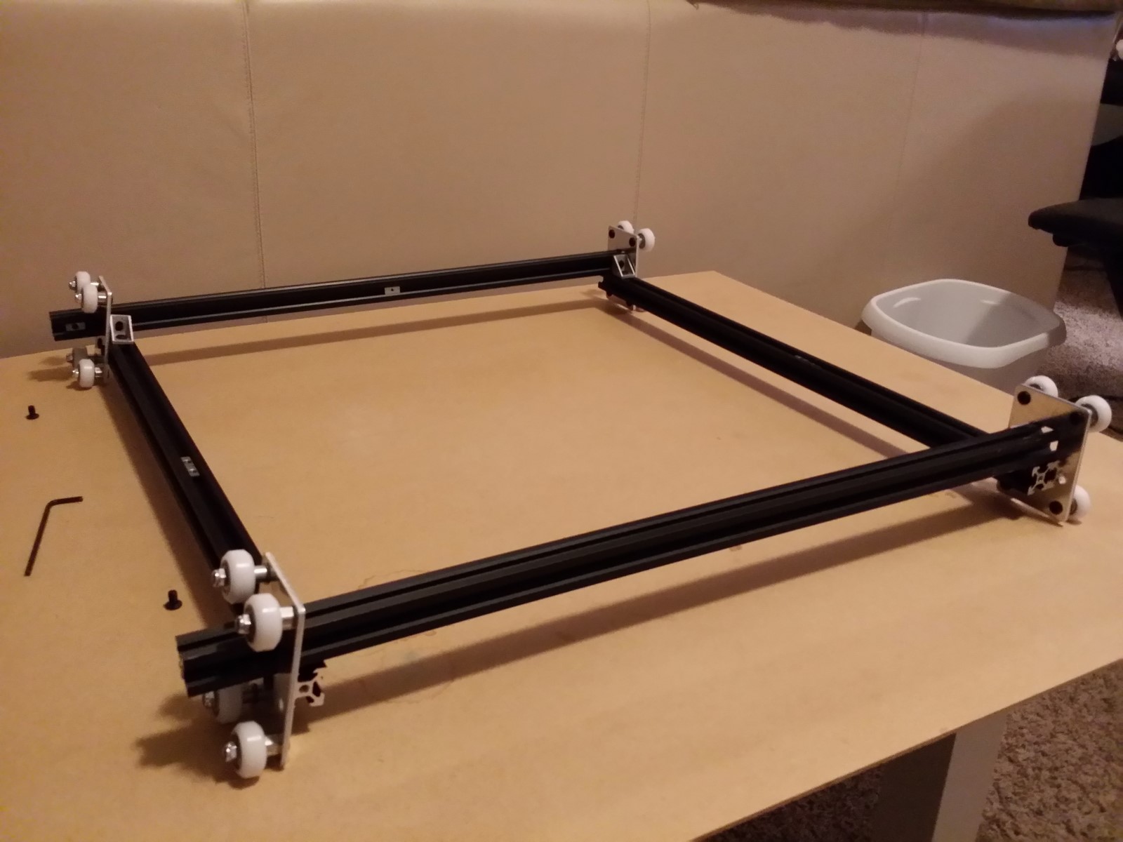
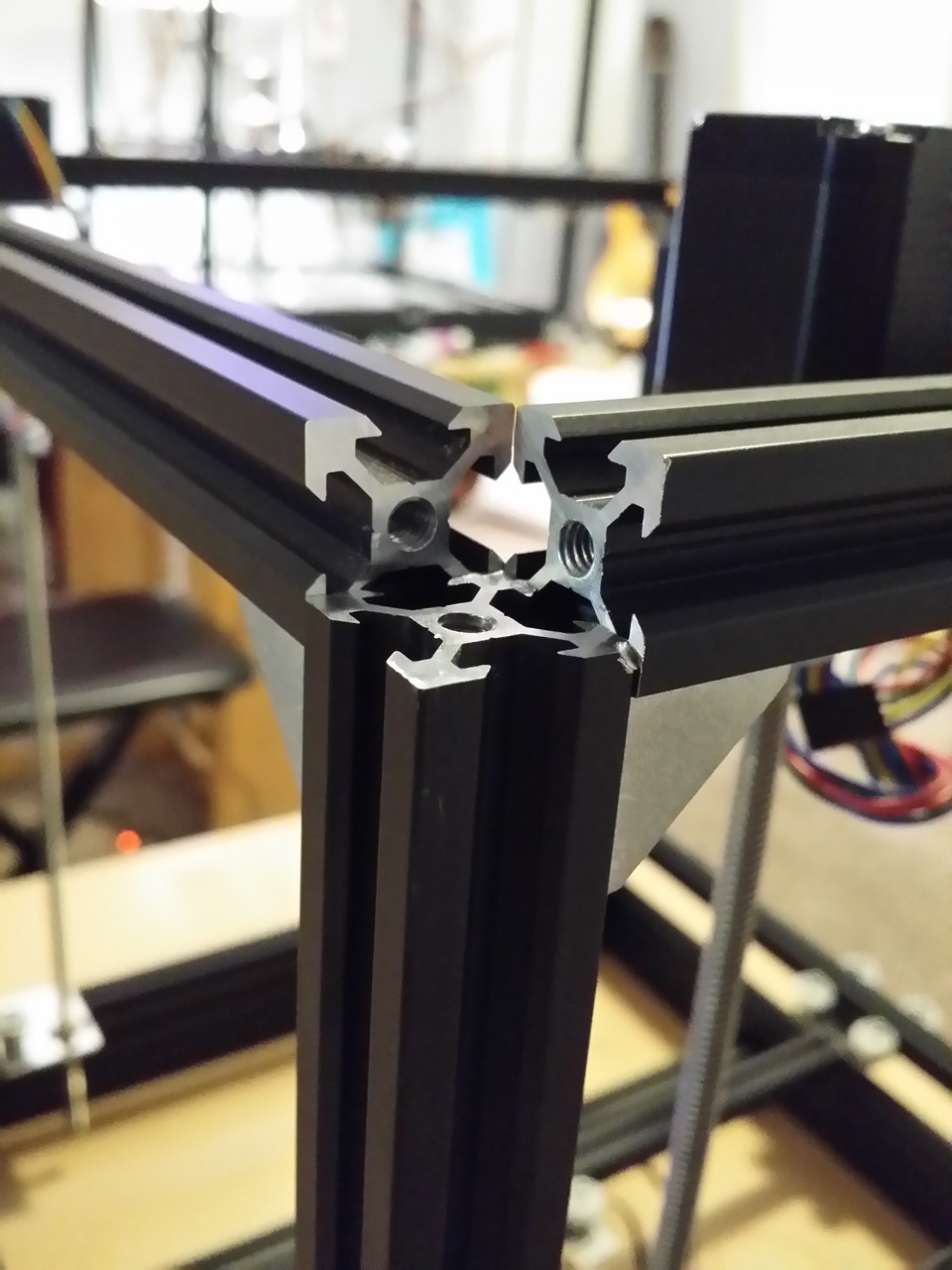
On your work surface, arrange the two rails holding the Z plates (big square
holes) parallel to each other and spread apart, with the wheels facing away
from each other and the longer box-hole section oriented upward. In between
these two rails, add in the two 551.5mm rails (double-check their length!) to
create a box shape, with the 551.5m rails on top and with their ends poking
through the box-shaped holes on the Z plates.
http://www.neveroddoreven.com/cobblebot/20150815_194759.jpg
On each of the two rails holding the Z plates, slide four T-nuts (flat side
away from rail) into the top slot and move them to the middle of the rail.
Using the outer T-nuts on the rail holding the Z plates, loosely fasten the
corner brackets using the bracket faces that still have their tabs, with the
ground-off faces oriented toward the 551.5mm rails. On only one 551.5mm rail,
insert a single M3 T-nut into the slot facing inside the box structure and move
it to the middle of the rail. Insert a T-nut (flat part facing away from rail)
into each end of both 551.5mm rails facing inside the box structure. Move these
T-nuts into position over only one of Z plate rails, and then slide the
grinded-smooth side of the corner brackets up against the 551.5mm rails on both
sides and screw them together loosely. Align the end of the 551.5mm rail so it
is flush with the outer face of the Z plate. Do not fasten the 551.5mm rails to
the other Z plate rail yet.
http://www.neveroddoreven.com/cobblebot/20150815_200721.jpg
http://www.neveroddoreven.com/cobblebot/20150815_201245.jpg
http://www.neveroddoreven.com/cobblebot/20150815_205003.jpg
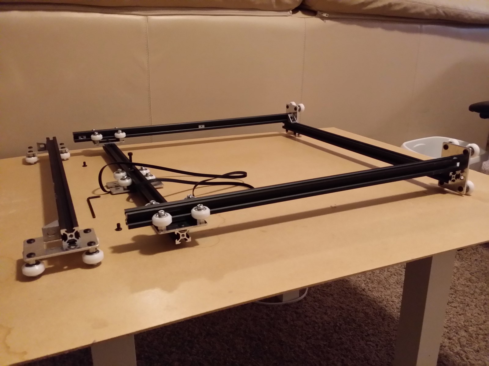
You now need to temporarily remove the unfastened rail with the Z plates and
set it aside. Align and mount the Y rail's X plate wheels onto the 551.5mm
rails with the Y plate facing down toward the work surface. Roll the Y rail
about 100mm down the 551.5mm rails, then stop. Loosen the screws holding the X
plates to their Y rail, then gently continue rolling the Y rail all the way to
the other side so that it meets up with the fully-fastened corner brackets. Do
this slowly or you risk bouncing your wheels against the corner brackets and
carving new dents in them.
http://www.neveroddoreven.com/cobblebot/20150815_205109.jpg
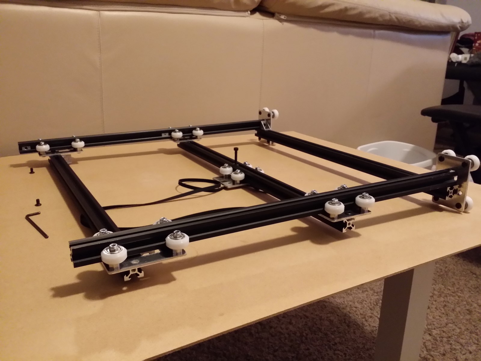
Take the Z plate rail that you recently removed and temporarily mount its
wheels onto the 551.5mm rails with their plates facing down toward the work
surface. Move the Z plate rail down the 551.5mm rails and push it up against
the Y plate. Ensure the Y plate rail is now trapped so that it can't roll
anywhere -- this helps to square up the X trucks on the Y rail while inside
this assembly.
http://www.neveroddoreven.com/cobblebot/20150815_205151.jpg
http://www.neveroddoreven.com/cobblebot/20150815_205216.jpg
Examine the Y rail on its ends.
· On a 1A kit, you will see the X plate's outer T-nuts kind of half-hanging out of the Y rail. Center the Y rail so that on both ends of the Y rail, those X plate T-nuts are equally exposed.
· On a 1B kit, you should be able to move the Y rail so that it's flush with the outer edges of the X plates.
Gently push the
rolling wheel assembly together so that the Y rail and X plates becomes trapped
and square with the assembly, and then give the X plate screws their final
tightening against the Y rail. Remove the remaining Z plate rail and attach it
a little more than finger-tight to the corner brackets in the same way that you
did the other one earlier. Perform a final check that you have two unoccupied
M5 T-nuts trapped inside the top face of both of the Z-plate rails, and one
unoccupied M3 T-nut inserted on the inside face of one of the 551.5mm rails.
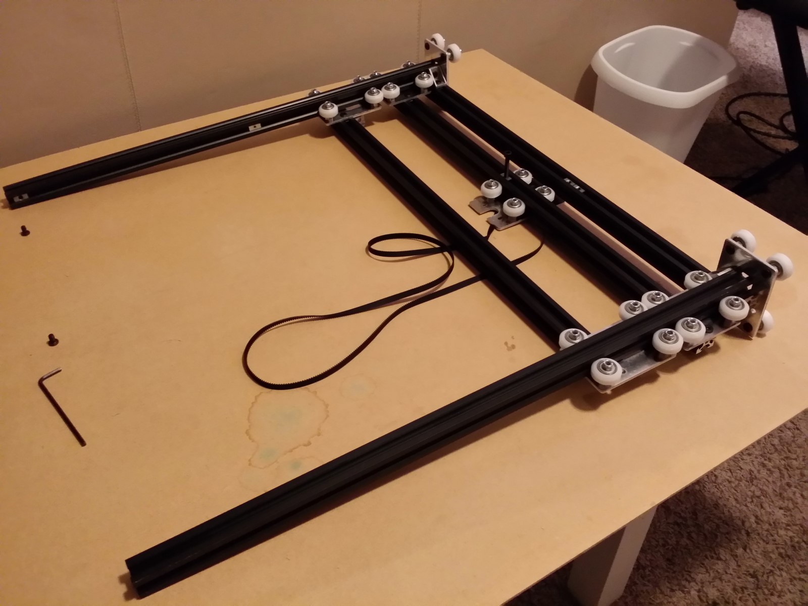
http://www.neveroddoreven.com/cobblebot/20150815_212442.jpg
Re: Building a working Cobblebot gantry
Posted: Sat Aug 15, 2015 2:20 pm
by neveroddoreven
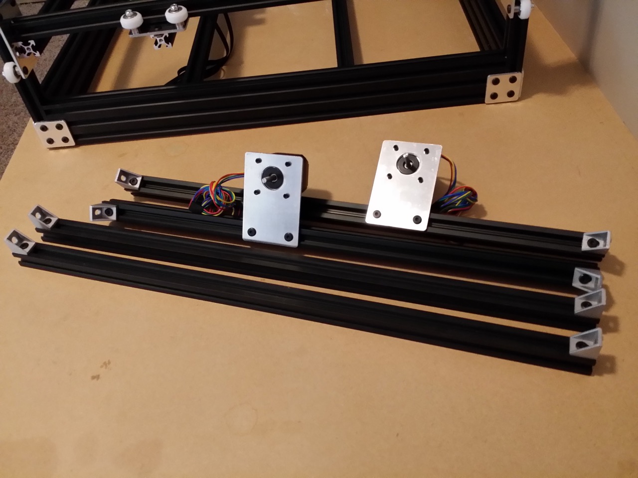
Part 5: Final Assembly
You will need to count out this stuff and set it out. Refer to the CB manual
for diagrams that identify the custom plates.
· The base frame and gantry cage that you've finished building
· The remaining four 20x20 rails (2@500mm, 2@560mm)
· 28x M5x8mm low profile hex screws (the manual called for 12x)
· 2x M5x25mm low profile screws
· 2x M5 nylon lock nuts
· 24x M5 T-nuts (the manual called for 4x)
· 2x 5x10mm M5 washers (CB stock)
· 4x 5x8mm M5 washers of the same type (either 0.5mm thick fiber ones or 1.0mm metal ones)
· 4x M5x20 socket head bolts, threads must go all the way to the head (you buy them, we save 4x Cobblebot M5x8mm bolts)
· 8x M5 plain full-height nuts (you buy them, these are not the Cobblebot nylon lock nuts)
· 8x
M3x10mm screws
-or- if you have 8x M3x12mm screws available, use them instead for a more
secure brass lead screw nut
· 16x M3x8mm screws
· 1x M3 T-nut (the manual calls for 1x)
· 8x M3 nylon lock nuts
· The remaining six roller bearings (2x 608, 4x 625)
· 2x Rigid couplers (aka small white boxes labeled "Resilient Coupling")
· 1x X motor mount plate
· 1x X idler mount
· 1x Y motor mount plate
· 1x Y idler plate
· 2x Z-motor mounts
· 2x brass lead screw nuts
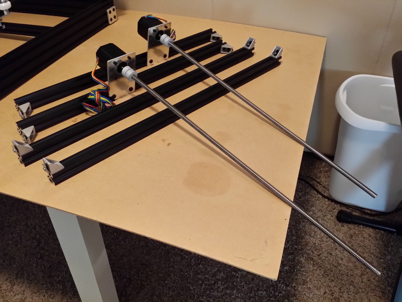
· 2x 8x500mm lead screws (wrapped in bubble sheeting, take special care of these
· 4x Bed clips
· 4x NEMA 17 Stepper motors
· 2x GT2 20-tooth pulleys
· 9x small zip ties (the four that CB included, plus five more of roughly the same size)
· Two short strips of electrical or masking tape
· Two 20mm wide by 360 mm long strips of 1/4 inch thick pressboard (or other extremely flat manufactured wood product with no grain) (no crumbly particle board, it swells too much in humid weather)
· 4x 370mm strips of 3/4 inch or greater width aluminum foil-type ductwork tape, kapton (polyimide) tape, or other high temperature tape
· 4x identical length unused hardwood carpenter's pencils, or four of some other stick-like objects that are >160mm long by at least 10mm wide on one side. These sticks must be factory cut (not moulded) to an identical length -- it's for calibration, and you want them identically-sized to within 0.2mm (0.1 or less is even better)
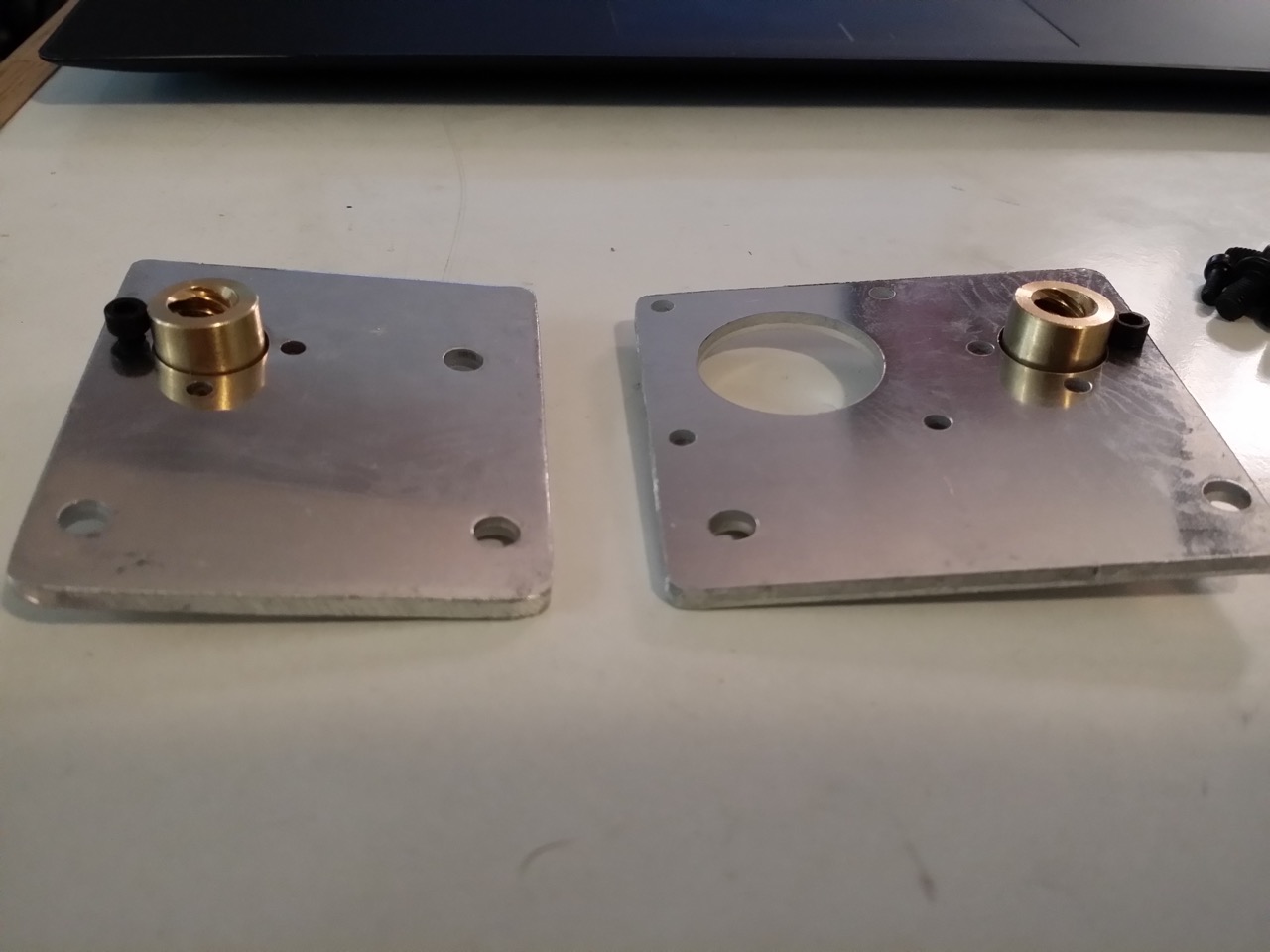
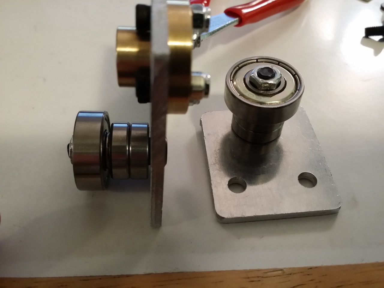
On your work surface, orient the X motor mount plate so the two M5 sized holes
are toward you and the largest hole is on the left. Next, orient the X idler
plate so the M5 sized holes are toward you and the largest hole is on the left.
Pick each plate up momentarily, set a brass lead screw nut out facing with the
neck up, and set plate down with the appropriately sized hole onto the brass
nut. Drop a single M3x10mm (or M3x12mm) screw down through one of M3 plate
holes and through the brass nut.
http://www.neveroddoreven.com/cobblebot/20150816_082230.jpg
You can now pick up the plates and loosely install an M3 nylon lock nut on the
end of each M3 screw. Install the remaining six M3x10mm (or M3x12mm) screws and
M3 nylock nuts, then tighten all the M3 nuts until they become snug (careful,
these M3 nuts will strip out easily). Don't worry about exact alignment of the
brass nut within the plate holes.
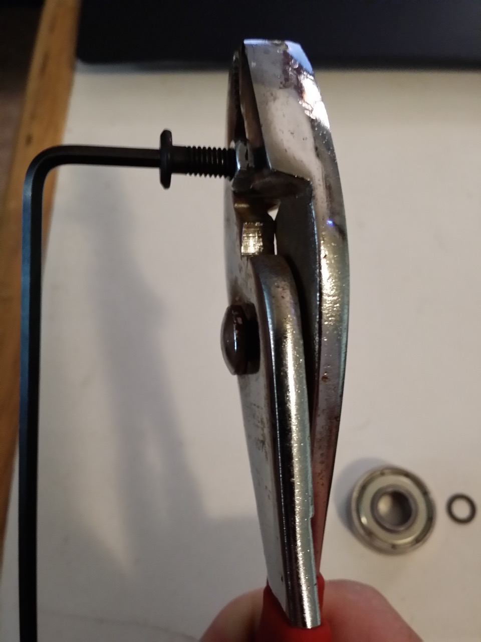
Using a hex key and a pair of pliers or wrench, thread the M5 nylon lock nut
onto a bare M5x25mm screw, with the nut's nylon part facing away from the screw
head. Tighten the nut all the way down to the screw head at a fairly brisk
pace, and then remove the nut from the screw. This primes the nylon part of the
nut for the next step.
http://www.neveroddoreven.com/cobblebot/20150816_091543.jpg
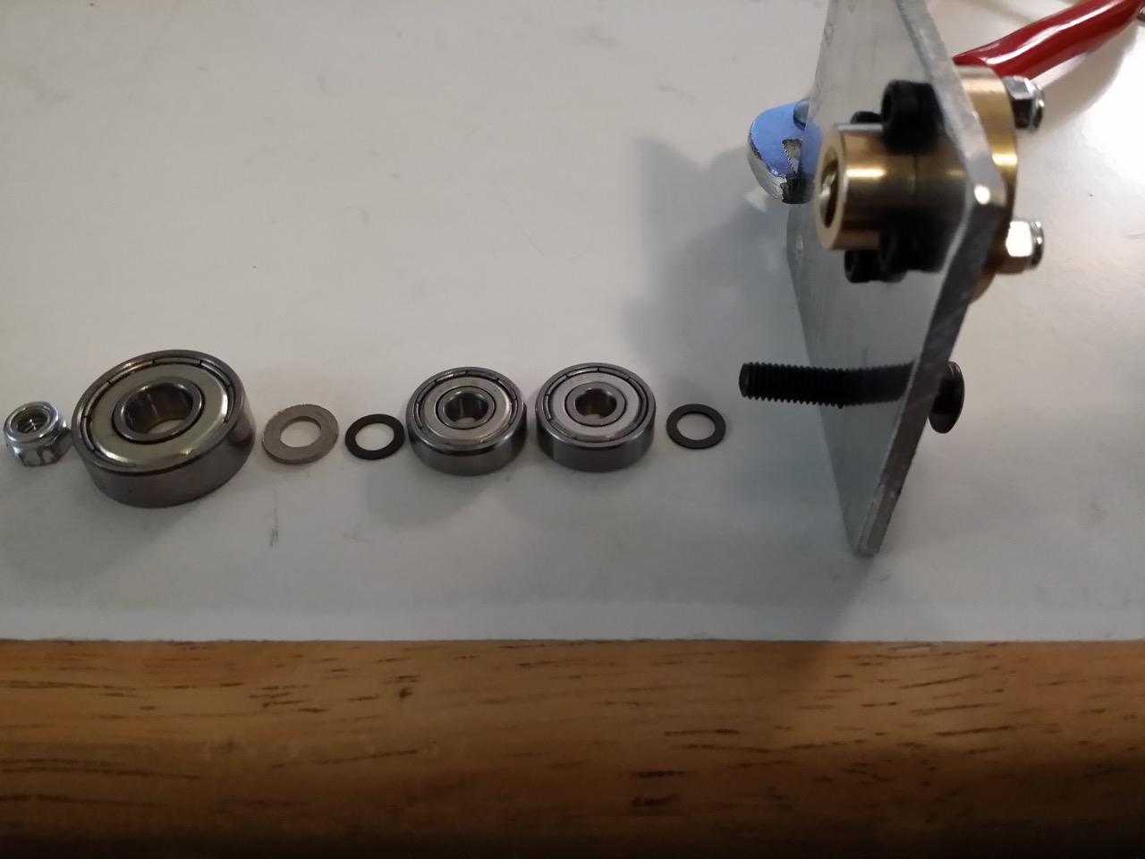
Insert the M5x25mm screw through the X idler plate M5 hole closest to the brass
nut, with the screw head on the same side as the brass nut head. On the exposed
M5 screw, place one 5x8mm washer, two 625 bearings, one 5x8mm washer, one CB
supplied washer with the stamp lip facing the 5x8mm washer, and one 608
bearing.
http://www.neveroddoreven.com/cobblebot/20150816_093729.jpg
Place the nut on the end of the M5 screw with the nylon part facing toward the
screw. Turn the nut counterclockwise until you feel it gently click into the
thread, and slowly thread the nylon part onto the screw until the nut's metal
parts engage the screw threads. Tighten the nut until its smaller nylon part sinks
inside and centers the 608 bearing, and the bearing assembly becomes one solid
stack that can still turn freely. You have just built the X idler assembly.
Repeat these steps using the same hardware on the single M5 hole in the Y idler
plate.
http://www.neveroddoreven.com/cobblebot/20150816_100131.jpg
Using four M5x8mm screws and finger-tight force, fasten the X motor plate and X
idler plate to the Z plate rails on the gantry cage that you finished in Part
4. There should already be two M5 T-nuts in the rails for this task. The plates
should be oriented as follows:
· With the X motor and idler plates hanging on the inside of the box
· Brass nuts oriented neck-up with the wheels and base-down with the Y plate
· Plates moved closest to the 551.5mm rail containing the unoccupied M3 T-nut
· Plates oriented with the brass nut furthest from the 551.5mm rail containing the unoccupied M3 T-nut.
· http://www.neveroddoreven.com/cobblebot/20150816_100407.jpg
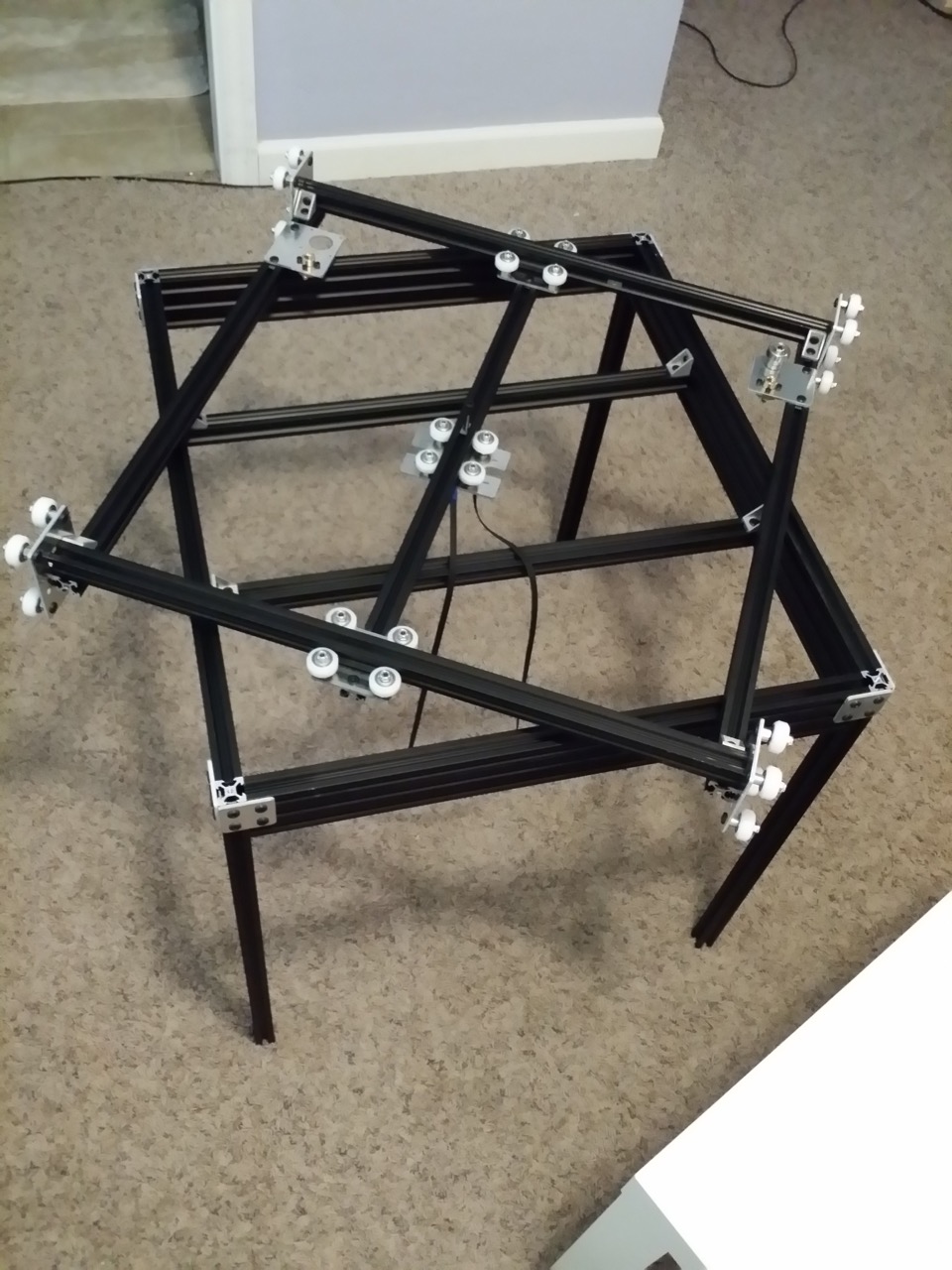
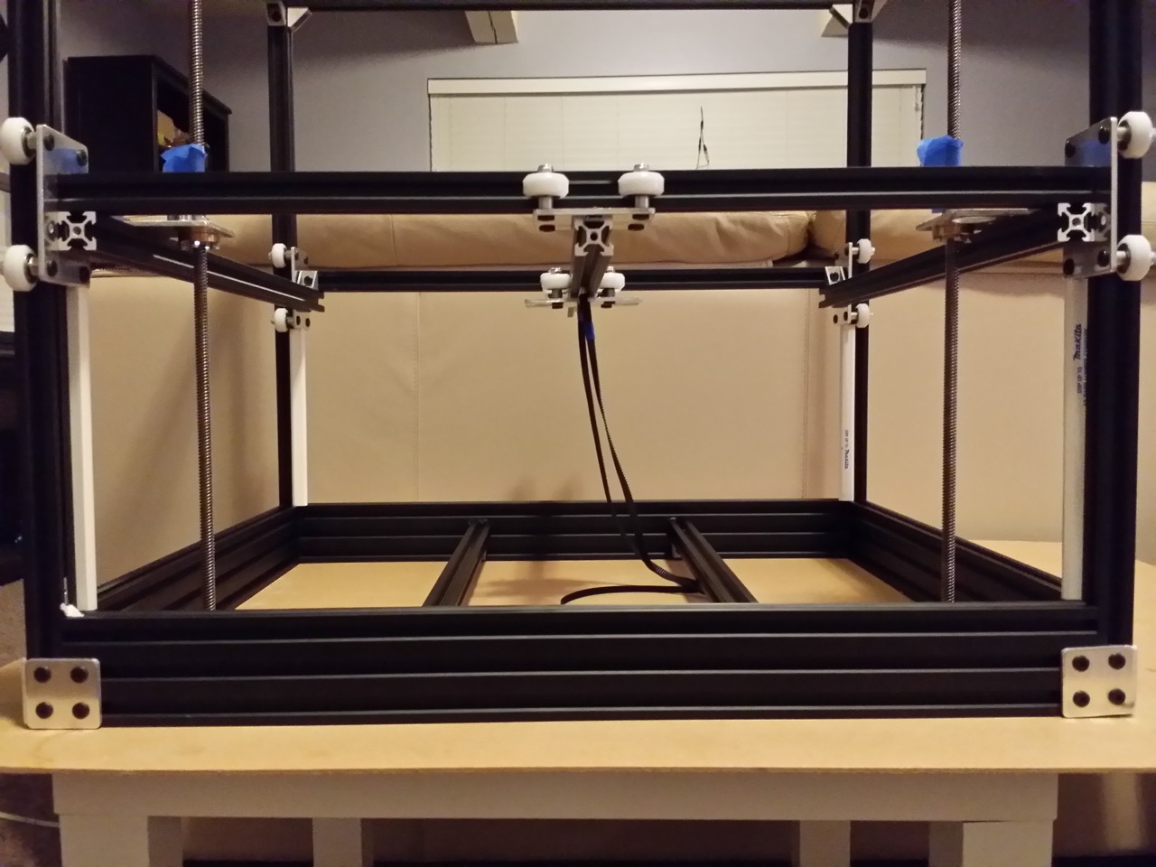
Turn your base frame upside down on a surface that won't damage the base
plate's vertical rails, to form a table. Place the gantry cage on the table at
a rotated angle to allow the Z rail wheels to hang off the sides.
http://www.neveroddoreven.com/cobblebot/20150816_101125.jpg
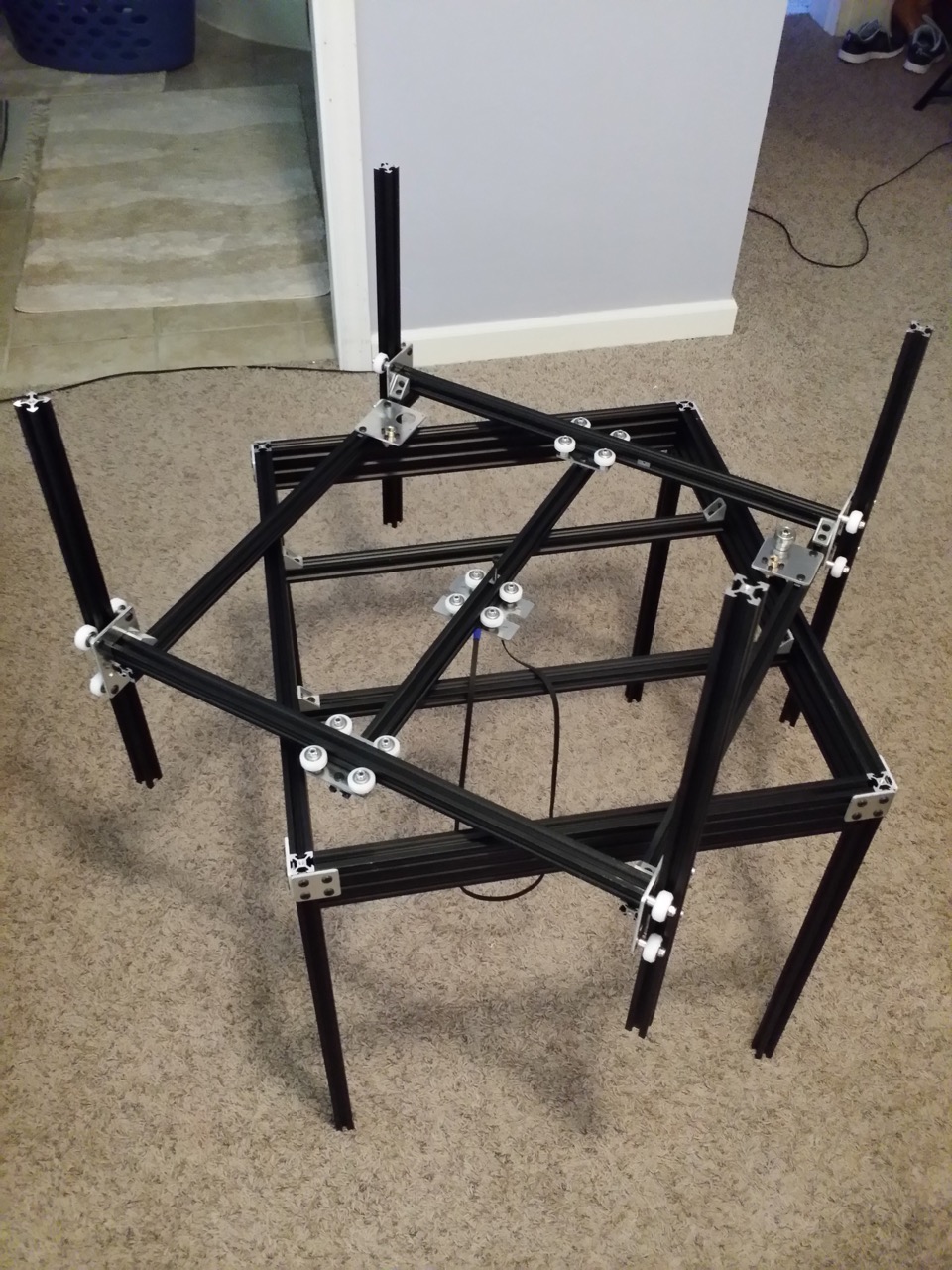
Take the four remaining free rails and insert one vertically into each Z truck.
Using the same techniques you used in Part 4 on the Y truck, tighten each of
these trucks up so there is no free play (remember to only rotate the eccentric
wheels toward the outside!). Once tightened, do not remove the free rail from
the Z truck -- you should end up with four free rails pinched in the Z trucks.
http://www.neveroddoreven.com/cobblebot/20150816_104145.jpg
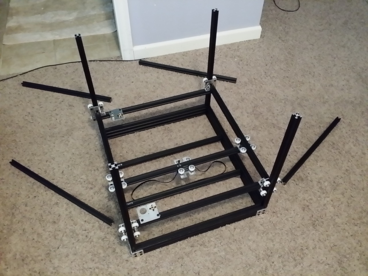
You will need a friend for the next step, or alternately a large
carpeted/padded floor area that can catch a falling rail without damaging it.
Pick up the gantry cage and set it on its side (on two of the free rails). Flip
the base frame over onto its base over a large padded area. Pick up the gantry
cage and turn it so the free rails are vertical and the the Y plate is facing
down. Carefully align the free rail ends on top of the base plate vertical rail
ends, and gently guide your gantry cage down the free rails and onto the top
area of the base plate. This process will liberate the free rails -- have a
friend pick them off, or you can nudge them to harmlessly fall away from the
frame and onto the padded floor. DO NOT push the gantry cage all the way down
to the base plate if it doesn't want to go, just let it glide down slowly to
its natural stopping point.
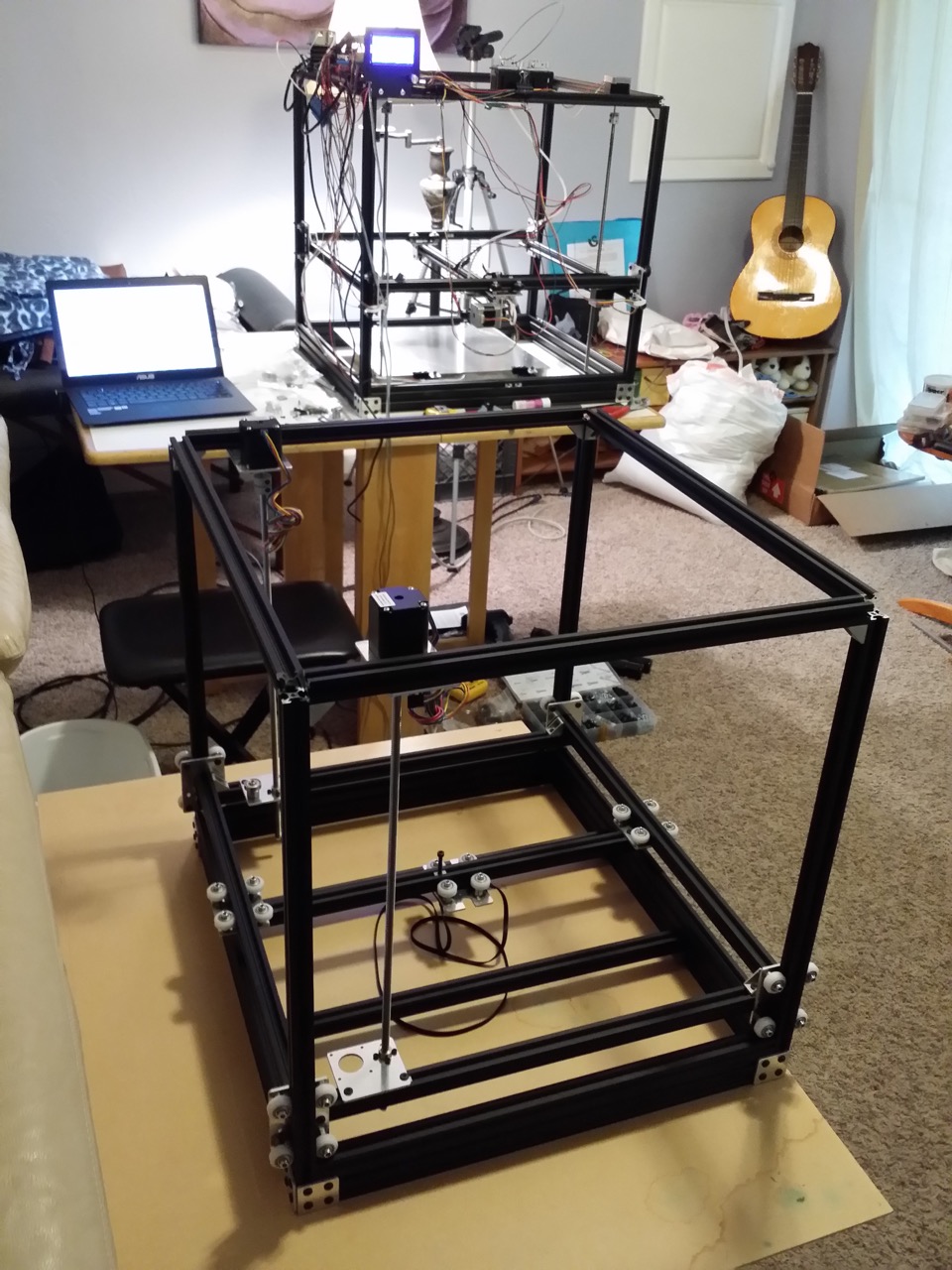
http://www.neveroddoreven.com/cobblebot/20150816_110806.jpg
On your base/gantry assembly, locate the 551.5mm rail that has the unoccupied
M3 T-nut, and slide the T-nut over so it is resting near to the X idler plate.
On the 20x60 560mm base frame rail immediately below, shove a small wad of
paper towel or tissue into the top slot, and then slide it firmly into the
corner below where the M3 nut and X idler is. Drop an M3 T-nut down the
vertical 20x20 rail so that it lands on top of the paper wadded corner.
http://www.neveroddoreven.com/cobblebot/20150816_112834.jpg
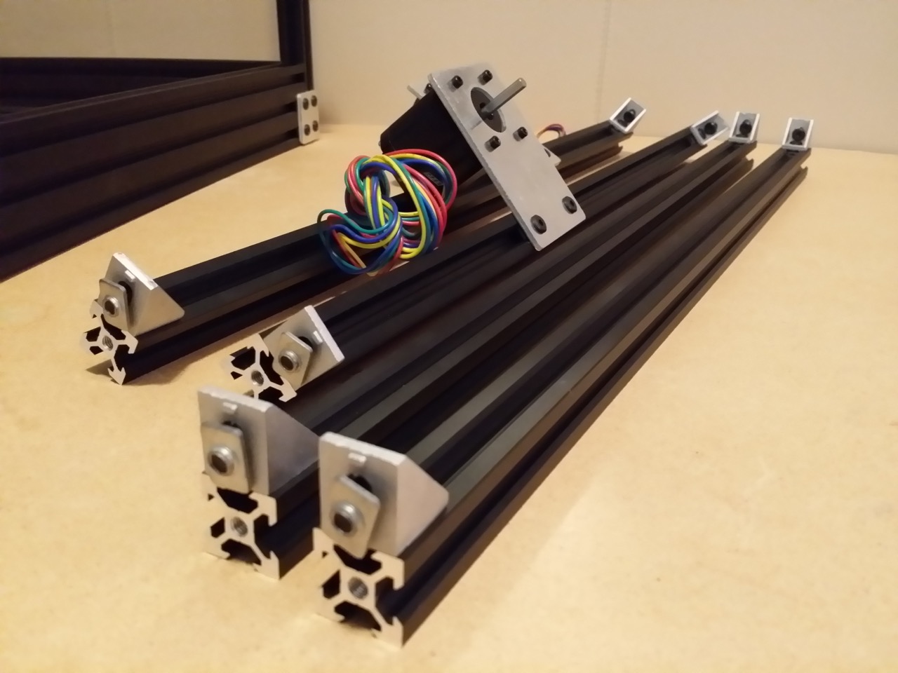
Collect the free rails and set them on your work surface. On the top slot of
each the shorter two rails, slide in two M5 T-nuts with the flatter side facing
away from the rail, and leave them in the middle of the rail. Install a pair of
corner brackets onto the top faces of all four free rails using a finger-tight
M5x8mm screw and an M5 T-nut, with the flatter side of the nut facing away from
the rail, and the flat sides of the corner brackets flush with the rail ends
and facing away from each other. Make sure the corner bracket face is
absolutely flush with the end of the rail -- you can stand the rail/corner
bracket on end on top of any other rail to bring them into alignment, and then
tighten the screw firmly.
http://www.neveroddoreven.com/cobblebot/20150816_122210.jpg
Install a NEMA 17 stepper motor into each of the two Z motor plates using four
M3x8mm screws, with the sharp lip of the plate facing away from the stepper
motor. CAUTION: Turn the screw in reverse until you feel it click against the
soft aluminum motor body, and then carefully thread it in and moderately
tighten. If your stepper motors feature removable wiring looms, leave the
wiring out for now or it will just get in the way. Loosely install the Z motor
plates using M5x8mm screws onto the available M5 T-nuts in the two shorter free
rails, with the motor and rail both sitting against the same side of the plate.
http://www.neveroddoreven.com/cobblebot/20150816_123013.jpg
On the free side of all eight corner brackets, very loosely install an M5x8mm
screw and T-nut with the flatter side facing toward the corner bracket (turn
the screw about 1.5 revolutions into the nut).
http://www.neveroddoreven.com/cobblebot/20150816_123657.jpg
Install the wider opened end of the rigid couplers onto one end of each lead
screw. Ensure the lead screw is fully seated, and tighten the rigid coupler
screw firmly. Stand the Z motor plates up with the Z motor spindles
horizontally, and tightly install each lead screw/rigid coupler onto a Z motor
spindle (the flat face in the motor spindle, if there is one, is unimportant in
this step).
http://www.neveroddoreven.com/cobblebot/20150816_124619.jpg
On each corner of the gantry cage, loosen the horizontally-oriented screws that
hold each of the corner brackets against the 551.5mm rail. The gantry cage will
become easier to move and fall to the base plate, so take care in handling it.
Also, the 551.5mm rail can easily slide back and forth through the Z plate
square holes, so take care to keep it aligned. The purpose of loosening these
screws is just to ensure the gantry rails are resting at the frame's base
without any compression or tension occurring between the gantry wheel trucks
and the vertical base rails. Raise the loosened gantry very carefully about
100mm, and ensure it can go back down freely and rest against the base. Tighten
all gantry corner bracket screws to a moderate level.
http://www.neveroddoreven.com/cobblebot/20150816_135325.jpg
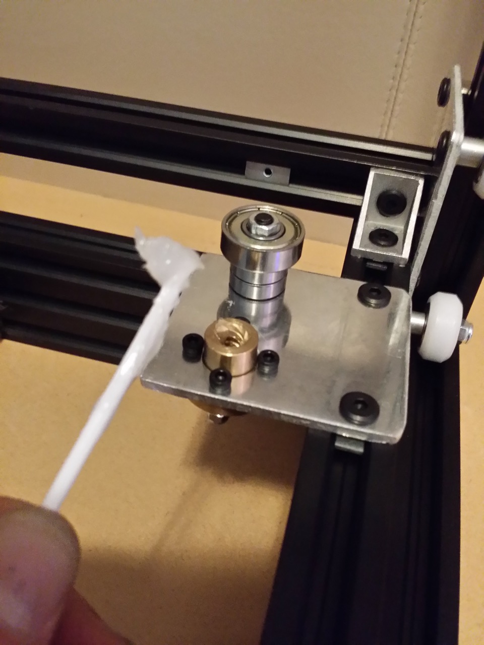
Take a cotton swab and cut the tip off, or use a discarded piece of zip-tie, to
spread a small blob of PFTE grease around the insides of the brass lead nut.
You don't need much for now -- we will grease the whole lead screw later.
http://www.neveroddoreven.com/cobblebot/20150816_140935.jpg
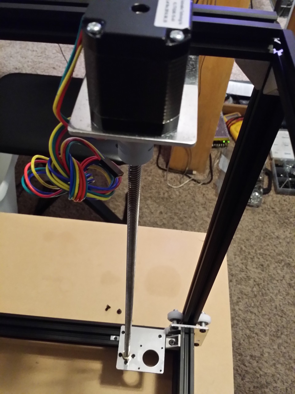
Loosen the Z motor plates on their rails. Install the four free rails on top of
the build frame, doing the rails with the Z motors first. As you are doing so,
you will need to align the Z motor plates on the shorter rails so the lead
screws are pointing down and thread easily into the lead screw nuts. Manually
rotate the rigid coupler to turn the lead screw into the lead nut, taking care
not to feed it in at an angle or scratch/damage the brass nut threads. Guide
the corner bracket T-nuts into the base frame rails. Align the sides of the
rails to be perfectly flush, and align the bottom edge of the top rails to be
4.5mm lower than the top of the vertical base rails. This gives you 15.5mm more
vertical build height and allows easier mounting of electronics on the top of
the printer, while sacrificing little to nothing in frame stiffness. It's best
to align and tighten one corner, then use the lead screw to adjust the height
of the other corner. Set the screws to a medium tightness.
http://www.neveroddoreven.com/cobblebot/20150816_143017.jpg
Now install the other two rails, also finger tight. Ensure that for each top
corner of the frame, the two freshly-installed rails have edges that meet
together. This ensures the top of the frame is exactly square with the frame
base. Double check all corners are aligned, and firmly tighten all screws in
the top corners. You have now completed the enclosed base frame.
http://www.neveroddoreven.com/cobblebot/20150816_144235.jpg
http://www.neveroddoreven.com/cobblebot/20150816_144319.jpg
Unscrew the X motor plate and X idler plate from the gantry cage, so they are
suspended from the lead screws. Ensure the Z motor brackets are loosened
slightly but still touching flat against the rail. Turn the rigid couplers to
raise the X plates slightly, and let them hover 1-2mm above the rails. Slide
the Z motor plate (taking the X motor plate below along with it) toward the
closest vertical rail until the X motor plate runs into the corner bracket.
Slide the Z motor plate back slightly to allow 1mm of space between the X motor
plate and the corner bracket. Tighten the Z motor plate and then turn the rigid
coupler to lower the X motor plate onto its rail. Screw down the motor X plate
with the outer edge aligned along the rail it mounts upon.
http://www.neveroddoreven.com/cobblebot/20150816_151359.jpg
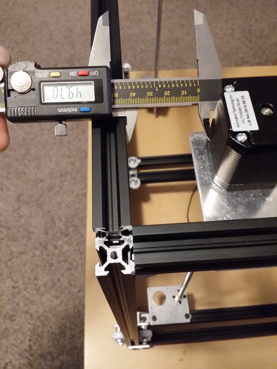
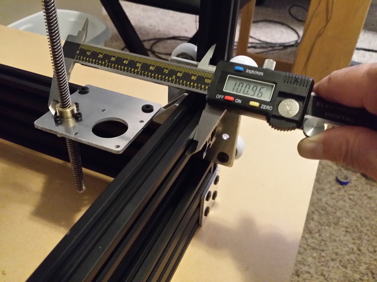
Using a digital caliper or a depth gauge, take the measurement of the distance
between the aluminum cast part of the Z motor body carrying the X motor plate,
and the top rail installed above the 551.5mm rail nearest to the lead screws.
Also take the distance between the 551.5 rail and the brass nut in the X motor
plate. Use your own distances -- don't use my measurements!
http://www.neveroddoreven.com/cobblebot/20150816_152555.jpg
http://www.neveroddoreven.com/cobblebot/20150816_152728.jpg
Reposition and tighten the other Z motor plate (taking the X idler plate below
along with it) to match the rail distance of the Z motor driving the X motor
plate, with the Z motor plate aligned along the rail it mounts on. Rotate the
other rigid coupler slightly to lower the X idler plate just barely onto its
rail. Observe the X idler plate, which should still be hovering over its rail.
Its brass nut should be about the same distance from the 551.5mm rail, give or
take 10mm, as the other brass nut. Flex the lead screw and X idler plate into
the same position, matching the other brass nut's distance from the 551.5mm rail,
and screw the X idler plate down firmly to the rail.
Dab a 1cm smear of PTFE grease onto one side of the lead screw every 50mm,
starting from immediately above the brass nuts all the way up to the rigid
couplers.
--IMAGE--
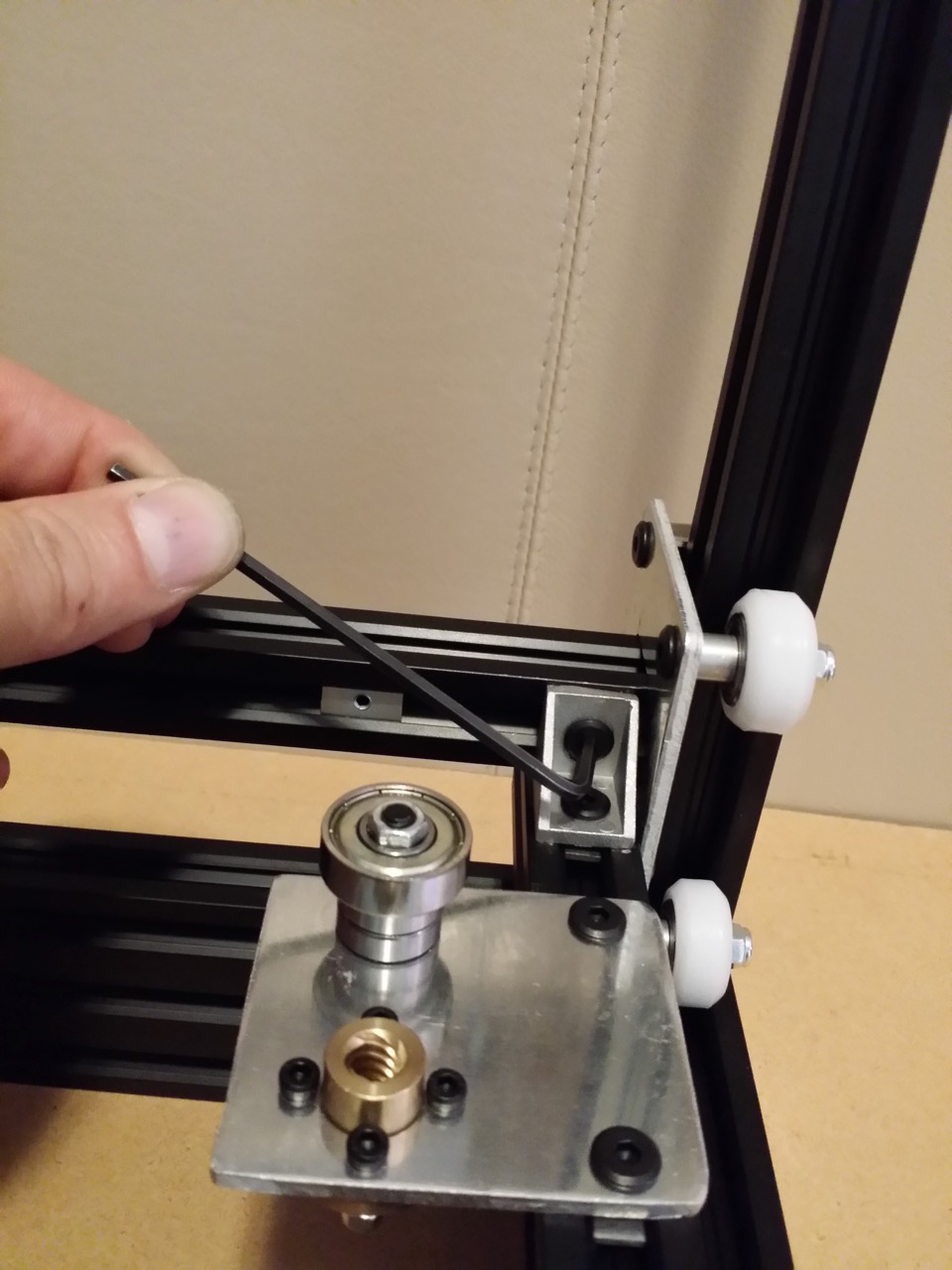
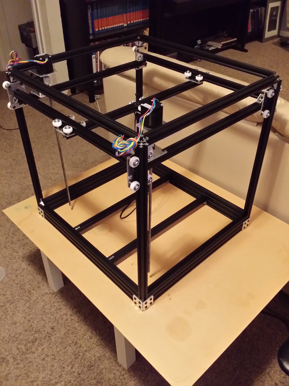
This part is tiring. Rotate both rigid couplers by hand at a matched pace to to
raise the gantry cage from the bottom to the top of the frame. Keep an eye that
the gantry cage stays level as it rises, or binding will occur on the Z trucks
or inside the brass lead nuts. It goes a little easier if a friend gives a
gentle helping lift to the center of the Y rail. You are checking that the
gantry shows no binding along the entire Z axis travel. At the half-way point,
loosen the Z motor plates at the top and adjust them to a directly overhead
position, which should relieve any built-up binding inside the brass lead nuts.
Do not loosen the X motor/idler plates. Continue raising the gantry cange, and
be careful at the top not to drive your wheels fully up into the sharp corner
brackets. Once the gantry cage reaches the top, move the Z plates around until
the lead screws are hanging straight down and the Z motor feels loose in its
position -- you are searching for the spot where there is no binding inside of
the brass lead nut. Tighten the Z plates to their rails, and double check the X
motor/idler plates are also firmly tightened. Your Z axis drive system is now
aligned.
http://www.neveroddoreven.com/cobblebot/20150816_202657.jpg
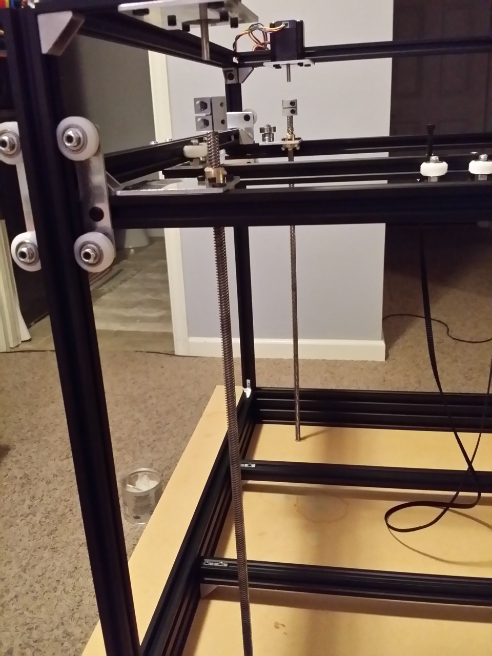
· NOTE: These next steps will get PTFE grease on your work surface. You can avoid this by putting scrap cardboard/newspapers underneath where the lead screws are.
Loosen (a lot) the
screws holding the top halves of the rigid couplers onto the Z motor spindles.
Use firm steady force and perhaps some Allen key leverage against the rigid
coupler screws to free the rigid couplers (and lead screws and gantry cage)
from the Z motors. Gently lower the assembly so it is resting on the bottom
ends of the lead screws.
http://www.neveroddoreven.com/cobblebot/20150816_203006.jpg
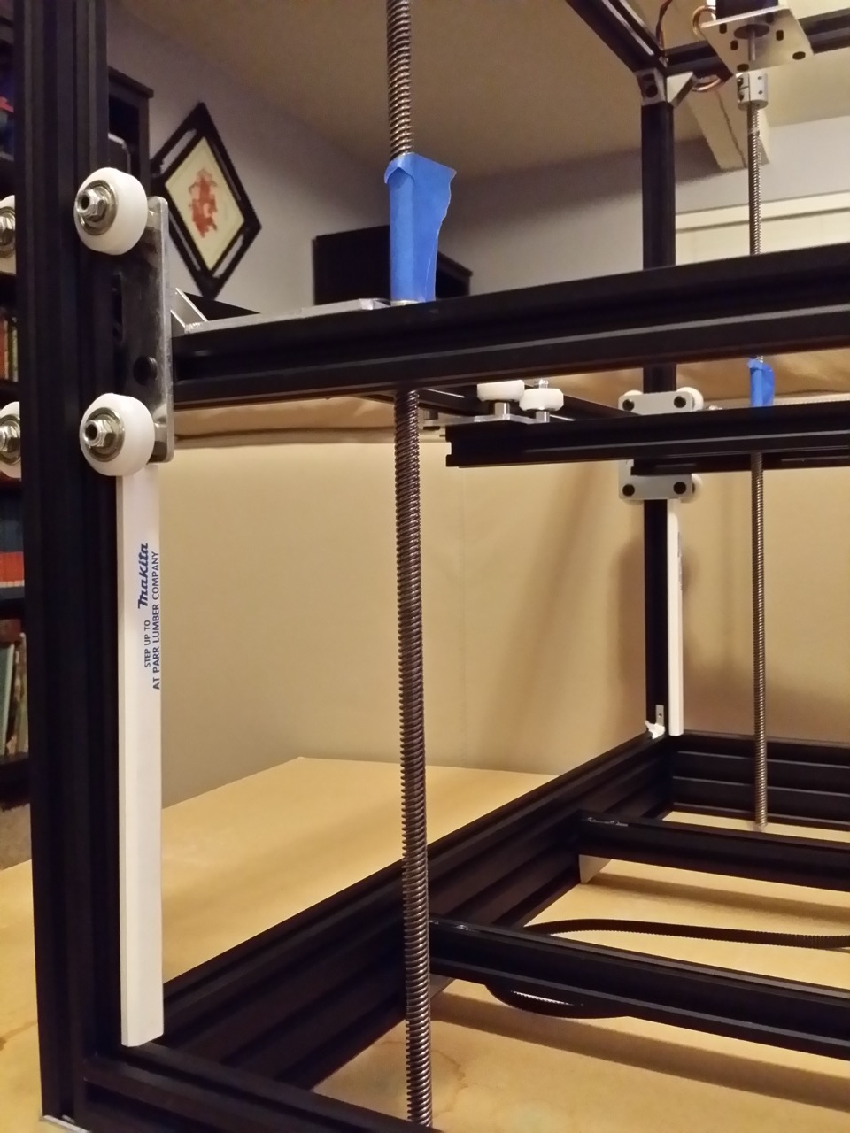
Take two of your four identical-length calibration sticks (ex: carpenter's
pencils) and set them standing up perfectly against the vertical rails nearest
to the Z motors. Rotate the rigid couplers to lower the gantry cage so that the
bottom edge of the Z plates come down and rest on top of the sticks. Rotate the
rigid couplers to raise the lead screws up from the work surface about 10mm,
and wrap a short piece of electrical or painter's tape around the lead screw,
just above the brass lead nut, to keep it from spinning back down on its own.
http://www.neveroddoreven.com/cobblebot/20150816_211641.jpg
Gently slide your other two sticks into the same position on the other side of
the gantry cage. Ensure that all four sticks are absolutely vertical, and not
going at an angle from the base frame up to the Z plate edge. It is very likely
that one or two of the sticks will easily fall out because the gantry is not
resting down upon it.
http://www.neveroddoreven.com/cobblebot/20150816_212007.jpg
Move the X and Y axes so the Y plate is centered inside the gantry cage, and
lift slightly on it. If a stick falls out with just the slightest lifting, that
corner is set too high compared to the other three corners. For that misaligned
gantry cage corner, loosen the two screws on its 90 degree corner bracket,
temporarily remove the stick, and briefly press down on the top of the Z plate
without disturbing any of the other corners/sticks. After the corner dips down
and returns to position, put the stick back, check that it now supports more
weight, and carefully retighten the corner bracket screws while pressing down
on the Z plate. Lift the gantry cage up, allow all the sticks to fall down, and
exercise the gantry up/down about 10mm or whatever the free travel allows at
this time. Put the gantry back down on the sticks again, and find the loosest
stick, and repeat the corner bracket adjustment. For a corner that just doesn't
want to fall into level with the others, you may need to loosen and the inside
screw holding the Z plate to its rail. If you still can't get it to align, try
loosening and retightening the corner bracket screws of one of the other
corners (only two corners at a time can ever be loosened!). Keep repeating
these steps until you find that all four sticks are equally supporting the
gantry cage. TIghten all the gantry cage corner brackets, and your gantry is
now square with the base frame. This step can take some time to get dialed in.
http://www.neveroddoreven.com/cobblebot/20150816_213615.jpg
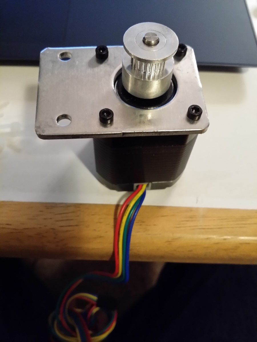
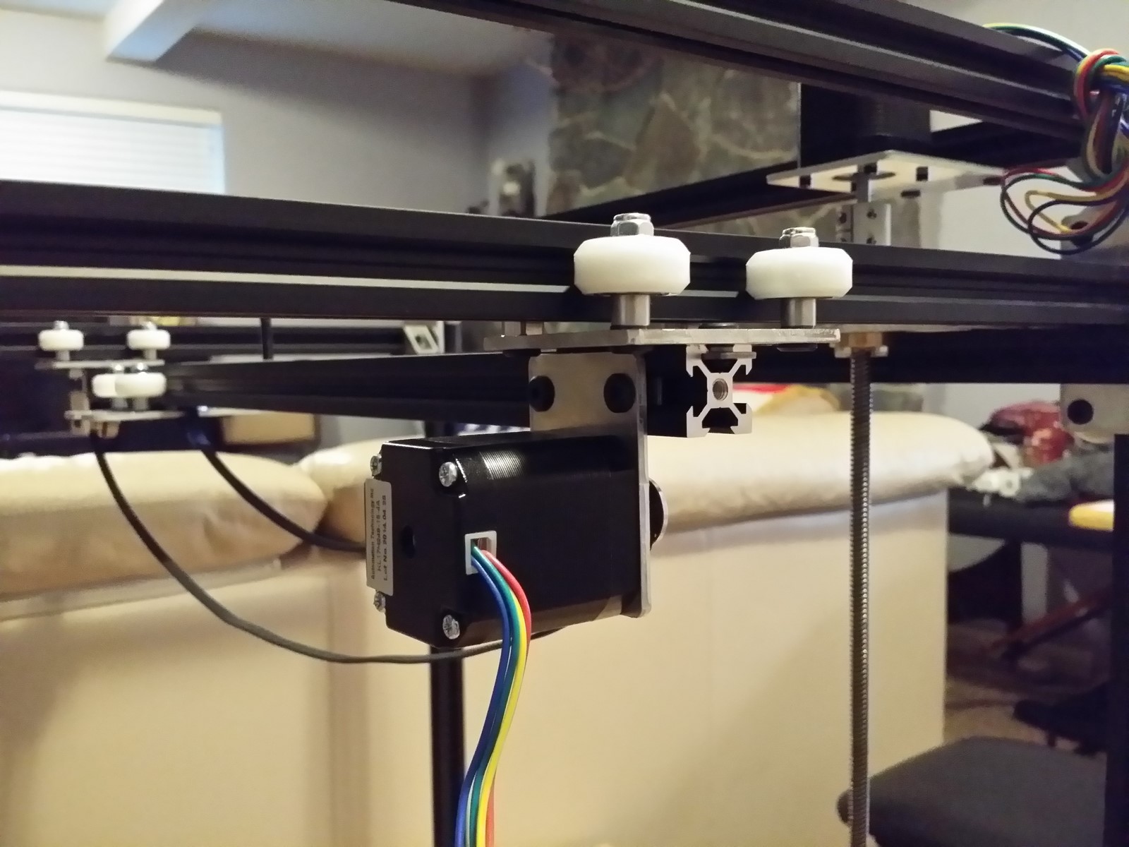
Mount a NEMA17 stepper motor to the Y motor plate using four M3x8mm screws,
with the sharp lip facing toward the motor -- orient it so the plate is
pointing to the left, and the motor is spindle-up with the wiring loom pointed
toward you.
http://www.neveroddoreven.com/cobblebot/20150819_195756.jpg
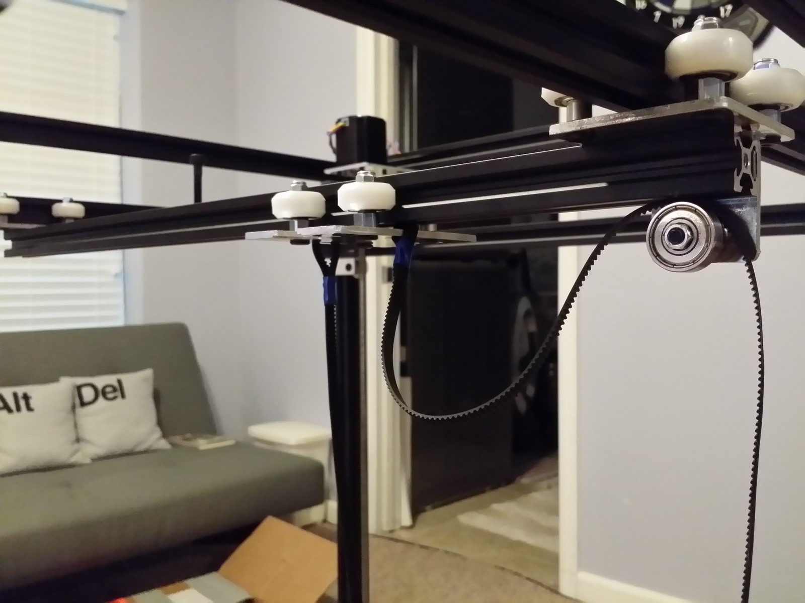
Loosely install one of the GT2 toothed pulleys on the Y motor spindle. Insert
two T-nuts (flat side out) into the Y carriage rail, on the end closest to and
facing toward the X idler. Insert two more T-nuts (flat side out) on the other
end of the same rail slot, and onto those install the Y idler with two M5x8mm
low profile screws, with the plate flush with the end of the rail, the bearings
hanging directly under the Y carriage rail, and the Y timing belt looped over
the 625 bearings before screwing the plate on.
http://www.neveroddoreven.com/cobblebot/20150819_193634.jpg
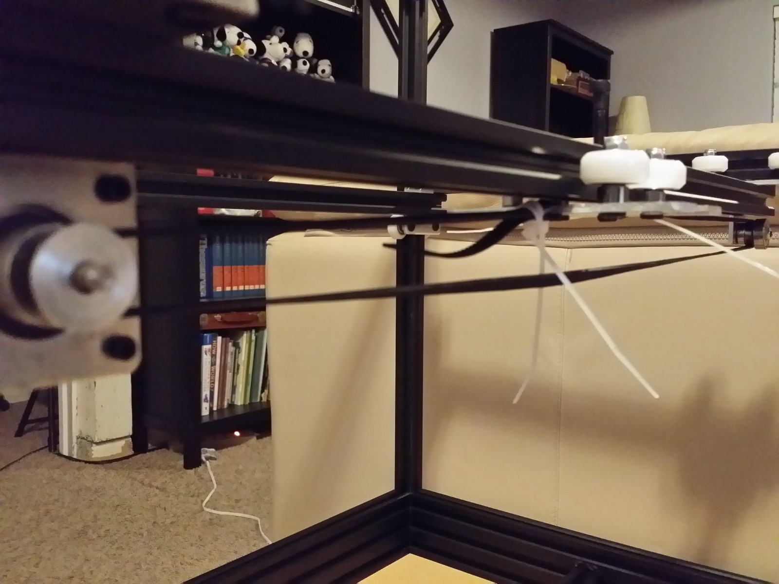
Install the Y motor plate on the opposite end of the rail using the T-nuts you
inserted earlier, with the motor spindle beneath the Y carriage rail, and the
motor bracket positioned 10-15mm from the end of the Y rail (you need room to
repeatedly tighten the motor against the belt).
http://www.neveroddoreven.com/cobblebot/20150819_200239.jpg
http://www.neveroddoreven.com/cobblebot/20150819_201217.jpg
Have two small zip-ties at the ready. Remove the tape holding the timing belt
onto side of the Y plate facing the Y idler, and zip-tie the belt against
itself with the teeth meshed together using two zip ties pulled very tightly
and moved up closely to each other. Try not to use up much slack in the belt,
to make the next step easier. Don't let the timing belt slip out of the Y plate
belt slot, it's not fun to fish it back through.
http://www.neveroddoreven.com/cobblebot/20150819_202424.jpg
Have two small zip-ties at the ready. Move the Y plate to the Y rail midpoint,
then loop the hanging-down belt over the Y motor pulley. Remove the tape
holding the timing belt to the Y plate, pull all the slack through, and
partially fasten both zip ties but leave enough room to pull it tight.
http://www.neveroddoreven.com/cobblebot/20150819_203622.jpg
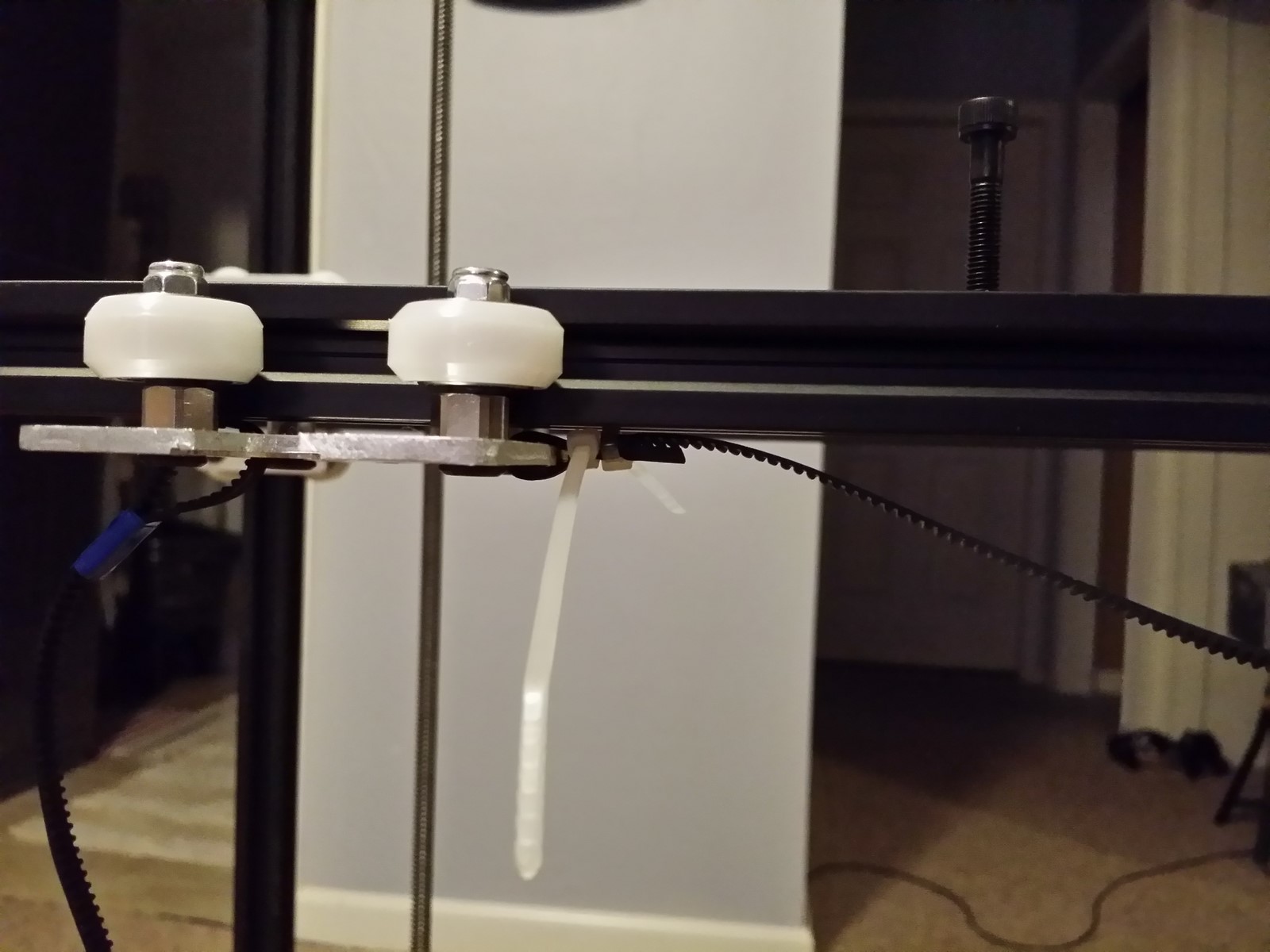
Now pull the belt firmly tight with one hand, and tighten down one of the zip
ties. Ensure the zip ties are butted up against each other, and tighten them
both firmly. Trim off the excess belt and zip tie lengths (caution: the belt
may break light duty wire cutters!). Loosen the Y motor plate, pull the Y motor
tight against the belt, and tighten the plate. With the Y rail at the midpoint,
the lower belt half is sufficiently tight if it makes a piano C2 pitch (65Hz)
when plucked. You will need to retighten it after a few hours of printing, and
again after probably 50 hours of printing once it's mostly stretched out. Move
the Y plate back and forth several times while watching the Y motor pulley.
Find the point where it wants to be most aligned with the Y idler, and tighten
its set screws at that location (or if it moves up against the Y motor plate,
move it out about 1mm before tightening).
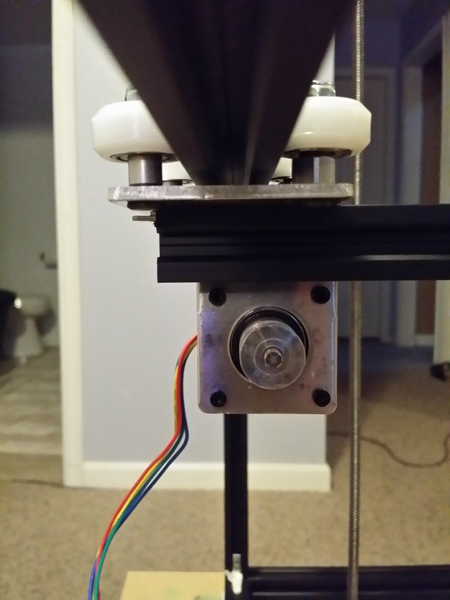
Install the X motor on the X motor plate using four M3x8mm screws, with the
motor spindle pointing up and the wiring loom pointing away from the Z screw.
Loosely install the X motor toothed pulley. Loosen and move the 25 (or 30) mm
screw standing on top of the Y rail, move it to stand between the X motor and X
idler, unscrew it all the way, and then thread it back into the T-nut for one
full revolution. Move the Y rail to be in the center of the printer frame. Install
the X belt using four small zip ties, using a similar fastening method as the Y
belt, and wrapping the belt around the upper end of the 25 (or 30) mm screw. As
you prepare to pull tight the belt and zip ties, ensure the standing screw is
lined up so that the belt loop is fairly straight on both sides. The screw will
lean hard to one side as you pull it quite tight and cinch down the zip ties.
Then firmly screw down the 25 (or 30) mm screw, and the Y belt tension should
become almost as tight as the X belt is.
http://www.neveroddoreven.com/cobblebot/20150821_202951.jpg
http://www.neveroddoreven.com/cobblebot/20150819_213453.jpg
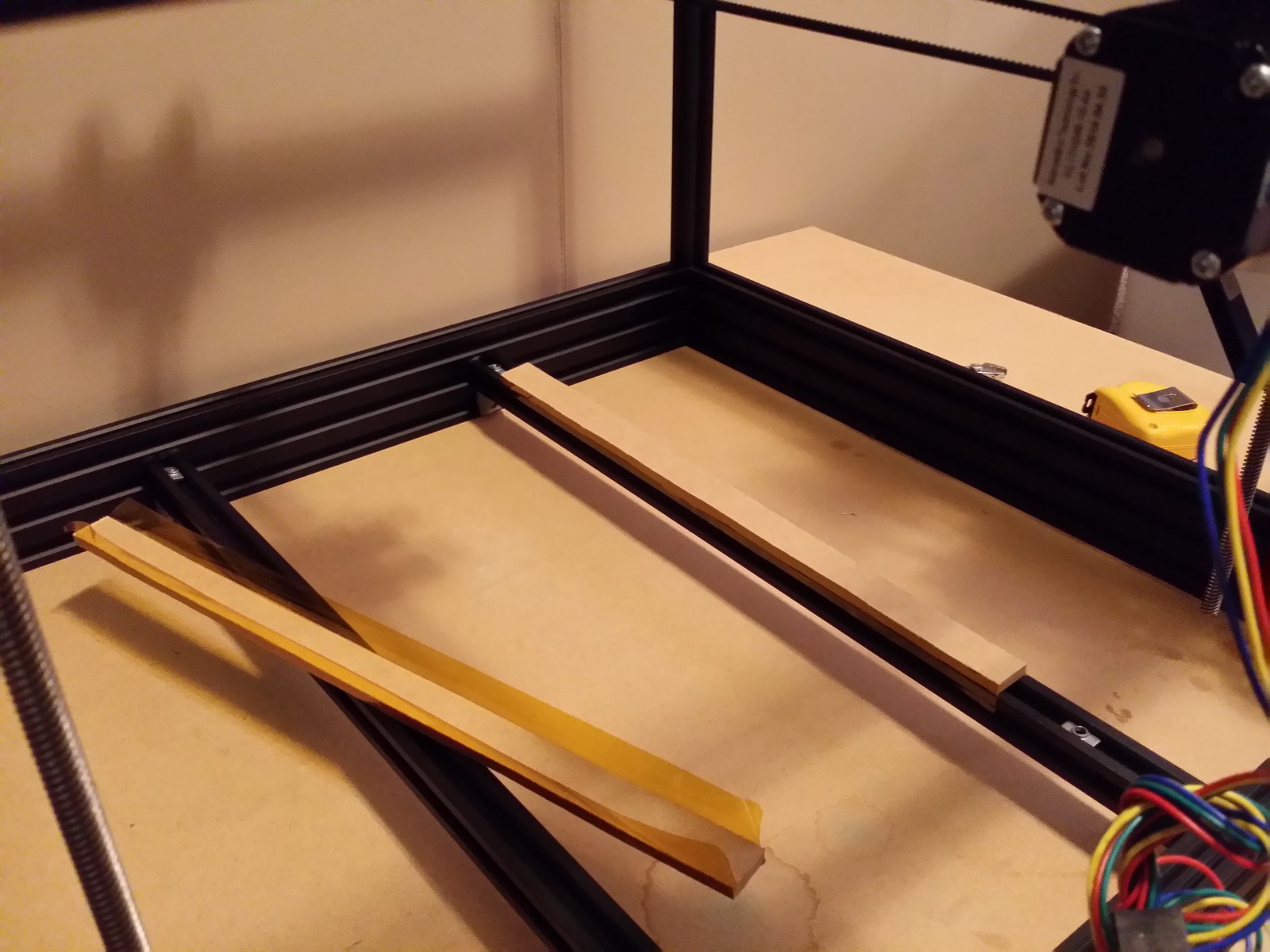
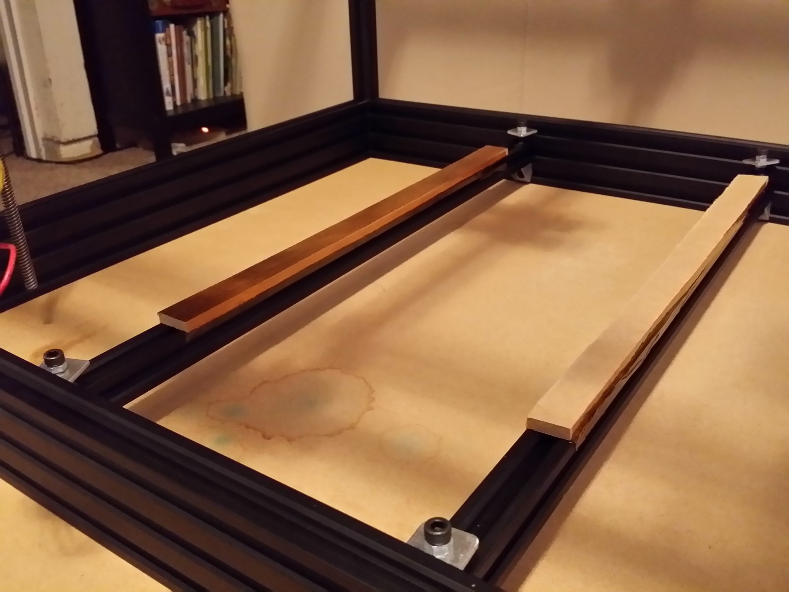
Move the T-nuts in the build platform rails to opposite sides (one against each
20x60 rail). Use a coarse file if needed to take any burrs or shredded fibers
off the long edges of the fiberboard strips, with the goal of having uniform
thickness down the length of the strips when laid flat. Lay the fiberboard
strips on the build platform rails, with their ends spaced 40mm away from the
20x60 base rail furthest from the Y motor. Use high temperature tape to tape
the strips to the build platform rails, along their sides, with absolutely no
tape wrapped onto the top surfaces of the pressboard strips. Take care not to
let any tape slip between the rail and the pressboard, to ensure they are
firmly pressed together.
http://www.neveroddoreven.com/cobblebot/20150821_211702.jpg
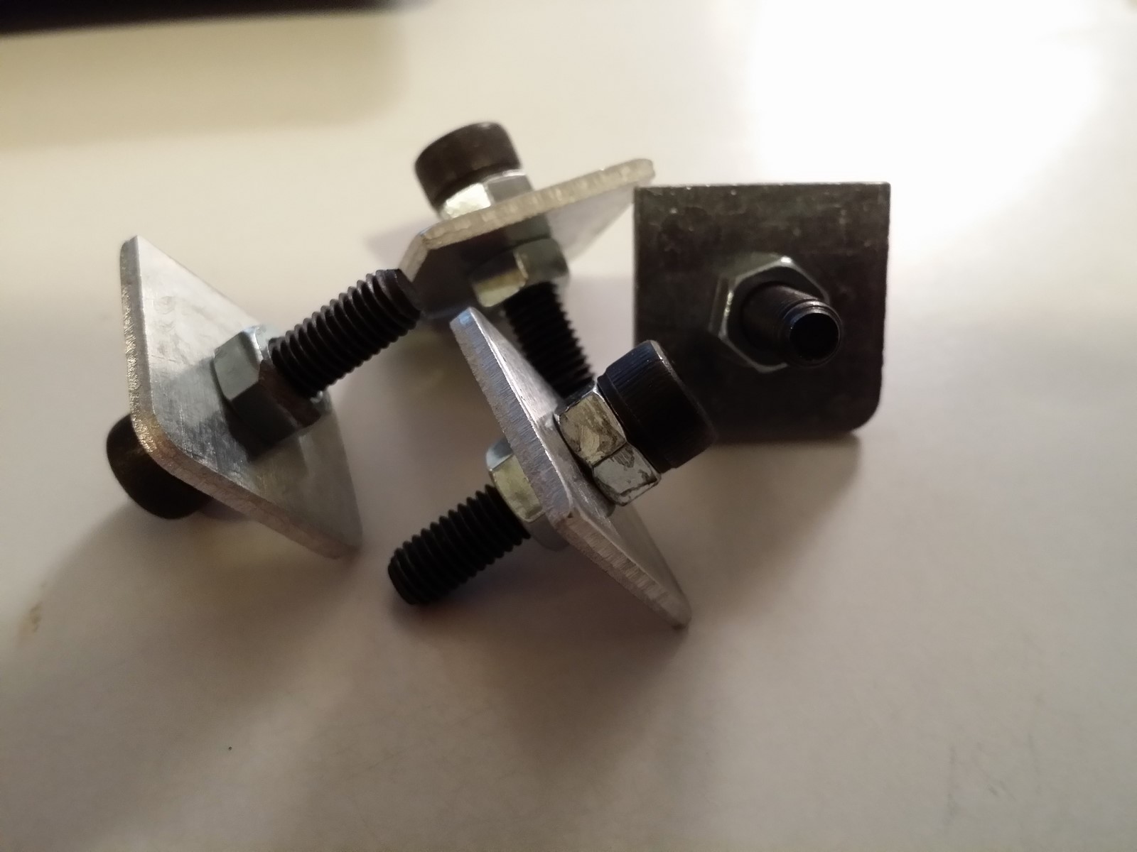
Thread one full size regular M5 nut fully onto each of the four M5x20mm socket
cap screws and firmly against the head. Insert the bolt through a bed clip,
sharp lip away from the screw head, and then screw on one more regular M5 nut
until the bed clip is trapped finger-tight between the nuts on the bolt shaft.
Thread the bolt ends semi-loosely into the unoccupied M5 T-nuts in the build
platform rails, and move the bed clips temporarily up against the 20x60 rails
to give you room to keep working.
http://www.neveroddoreven.com/cobblebot/20150821_213310.jpg
http://www.neveroddoreven.com/cobblebot/20150821_213448.jpg
One of my build plates arrived oppositely cupped in two perpendicular
directions, but I got it to a pretty flat state pretty easily. For one cupped
direction, I held it out in both hands so that the crest pointed toward me,
stuck out my gut, and pressed the plate up against my gut until I could feel
the plate begin to flex. I flexed the plate gently in around four zones evenly
across its surface, frequently checking the surface with a straightedge until
it was fairly flat in that direction. It took about four or five rounds of
gentle flexing to get it flat. Then I worked on the other cupped direction. Any
remaining imperfections should be taken care of by the glass plate going over
it and some liberally applied bulldog clips around the edges.
--NO IMAGE!--
If you are installing a mains (wall) voltage silicone heating mat:
Clean any dust or oil from the side of your aluminum build plate that has the
most scuffs and scars. Stick the silicone mat in a centered position on the bad
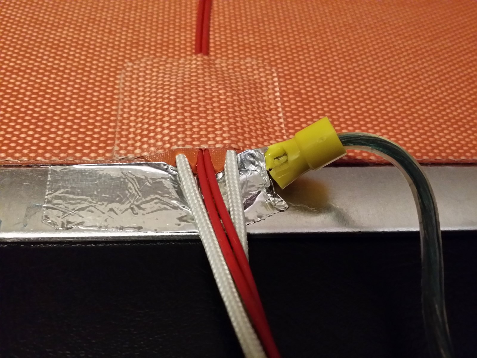
side of the build plate. Take a one-meter piece of insulated 18AWG or better
wire, crimp a spade or lug terminal connector on one end, and attach it to the
build plate for grounding purposes. You must do this in some manner without
deforming the plate or having anything sticking up from the other side.
Soldering the wire to the plate with a torch seemed like a heat deforming risk,
so I decided to lightly wedge it under the part of the silicone mat where the
wiring loom exits and firmly affix it down with aluminum foil tape. This
yielded a good 0.8 ohm connection between the plate surface and the far end of
the grounding wire. I do not know if this method works well in the long run,
and cannot confirm if it is a secure and safe solution. You should find your
own grounding solution, at your own risk, and you should check up on it
regularly. Failure to connect the plate (and the frame) to earth ground is a
risk because your mains circuit breaker won't be able to quickly pick up on
(and circumvent) a heating mat short to the frame or plate.
http://www.neveroddoreven.com/cobblebot/20150821_220113.jpg
http://www.neveroddoreven.com/cobblebot/20150821_221016.jpg
If you are instead installing some other kind of heating element:
Have fun installing it! Afterward, move to the next set of steps.
Continue on here, whether or not you have a heated bed.
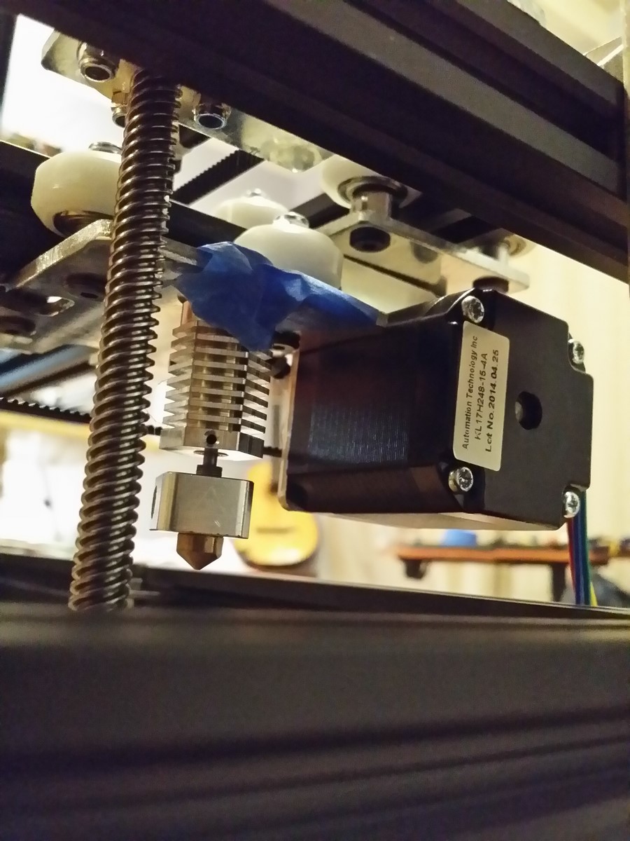
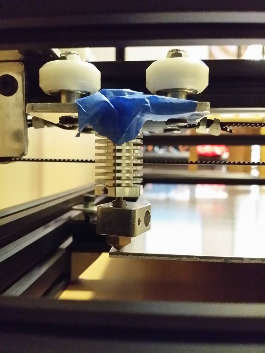
Temporarily place a hotend into the cutout side of the Y carrier plate that
faces toward the X idler plate and tape it into place using electrical or
painter's tape. Move the Y carrier plate into a position where it is gently
touching against both the Y motor and the X idler plate's Z screw.
http://www.neveroddoreven.com/cobblebot/20150821_224814.jpg
Move the Y carrier plate away from the Z screw by about 1mm. Hold the X motor
pulley firmly so it cannot rotate, move the Y carrier plate until it gently
touches against the X plate on the opposite side, and then pull the Y carrier
plate away from the X plate by about 1mm.
http://www.neveroddoreven.com/cobblebot/20150821_225010.jpg
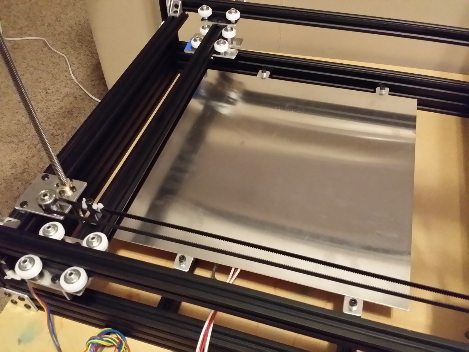
Place your build plate temporarily on top of the pressboard strips without
disturbing the hotend nozzle or gantry cage. Turn the Z motor rigid couplers
until the nozzle is about 10mm above the build plate surface. Position the
build plate corner directly below the nozzle, then temporarily drop the nozzle
down to about 2mm from the build plate to confirm the nozzle tip is over the
build plate and about 5mm away from the corner (not exactly on the corner).
MOVE THE NOZZLE BACK UP to prevent accidental damage. Set the build plate
straight within the frame, you can confirm this with calipers, a depth gauge or
tape measure to check for uniform distance between the build plate along one of
the 20x60 base rails.
http://www.neveroddoreven.com/cobblebot/20150821_231630.jpg
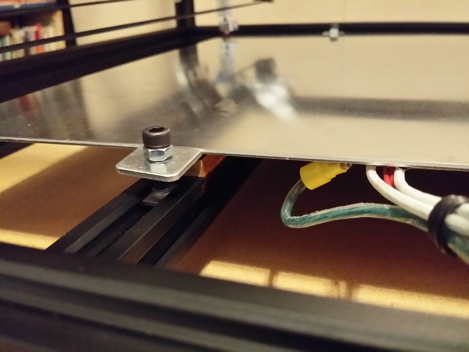
Slide your bed clips along the build plate rails until they are pressed against
the build plate edge, so the build plate cannot easily slide around on the
rails. If you are not installing a heating element beneath the build plate, you
will need to adjust the bed clip screws' M5 nuts downward until the bed clips
are captive between the nuts and also level with the build plate (some washers
on the screw might help). Moderately tighten the M5 screws into place. If you
are installing a heating element, don't let the clips slide up over the build
plate during this step. Re-confirm the nozzle placement, then move the gantry
up about half way to get it safely out of the way.
http://www.neveroddoreven.com/cobblebot/20150821_232749.jpg
http://www.neveroddoreven.com/cobblebot/20150821_232811.jpg
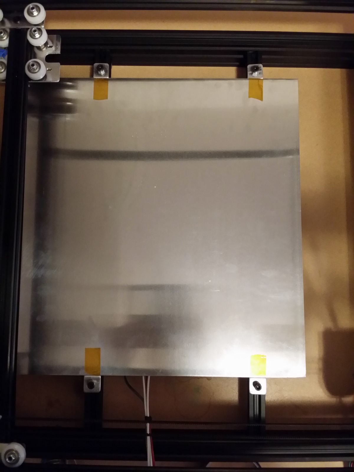
Use four small pieces of 3/4" tape to mark at the edges exactly where the
build plate sits over the rails.
http://www.neveroddoreven.com/cobblebot/20150821_233047.jpg
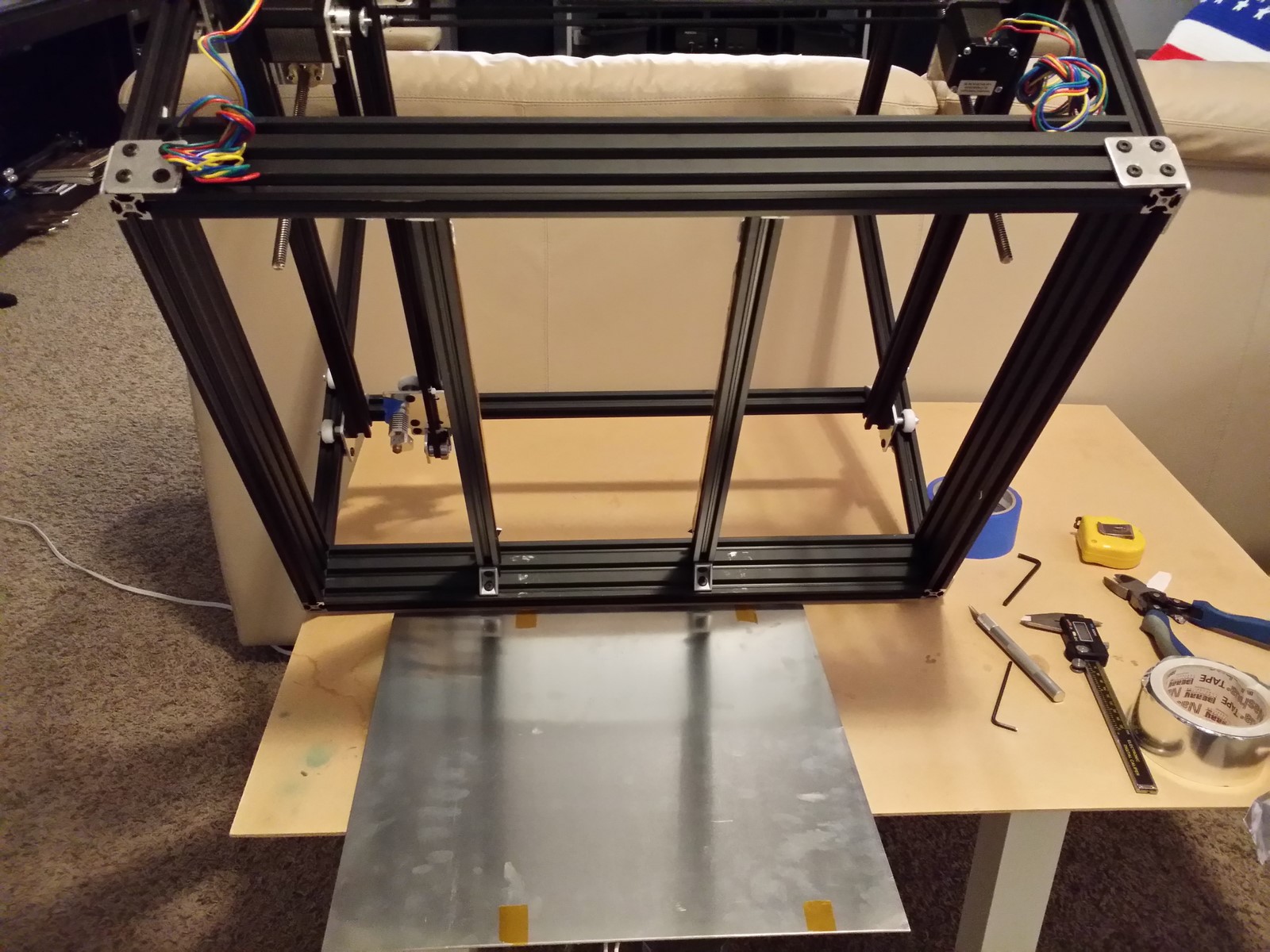
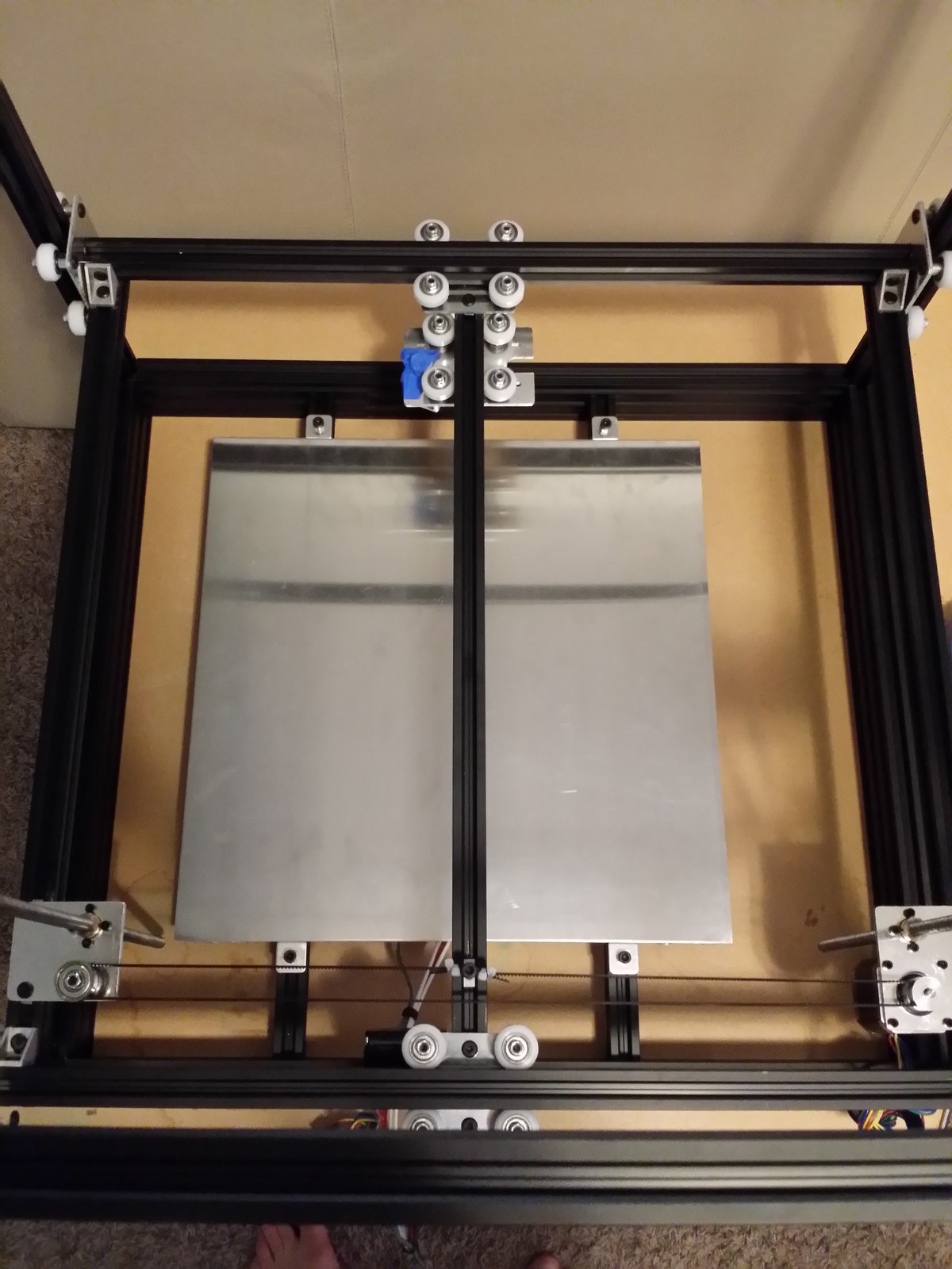
Tilt your frame up against a wall, or have a friend hold it at an angle, or
hang one side off the edge of your work surface. Place the build plate beneath
the printer with the tape marks roughly lined up below their rails. Loosen the
build plate rail brackets and reposition them to more evenly support the build
plate, spaced around 210mm apart and centered respective to the build plate.
Push the rails upward so they are flat and at their highest point, and
re-tighten the brackets.
http://www.neveroddoreven.com/cobblebot/20150822_083850.jpg
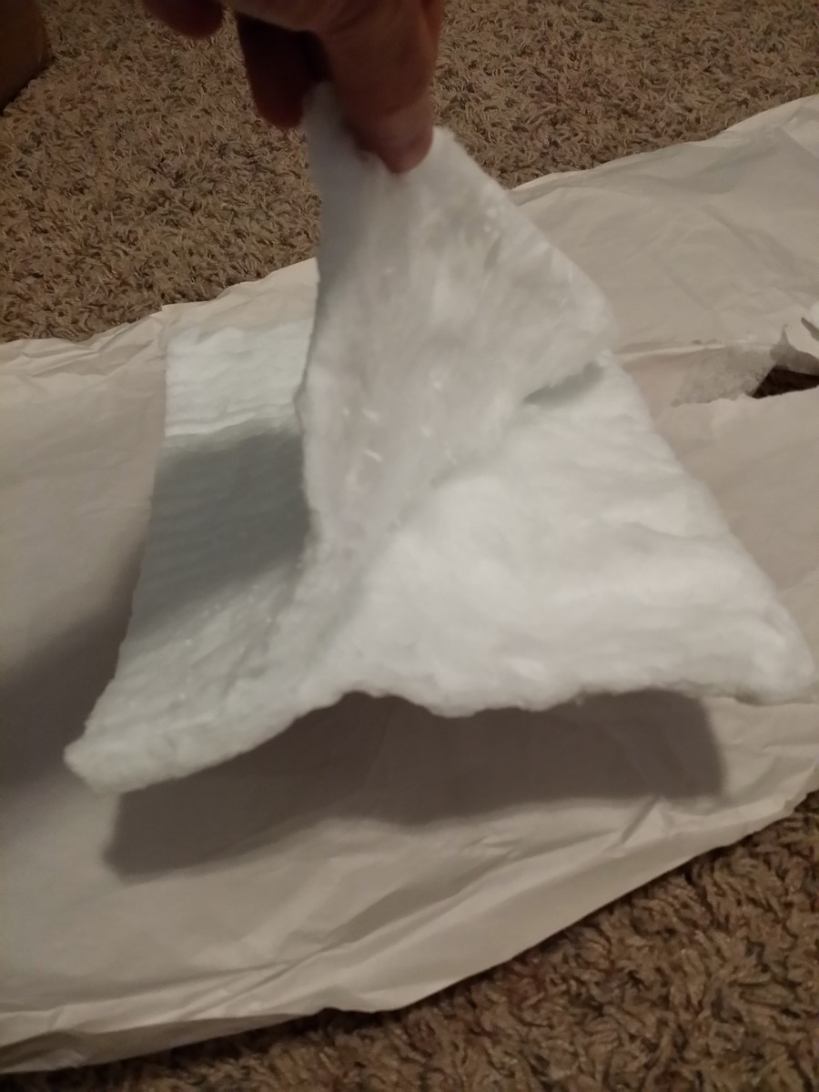
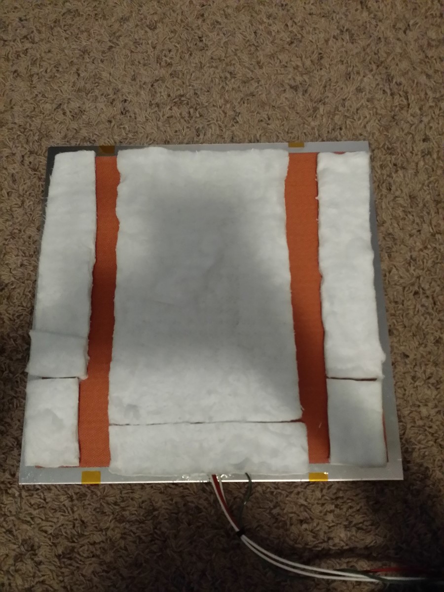
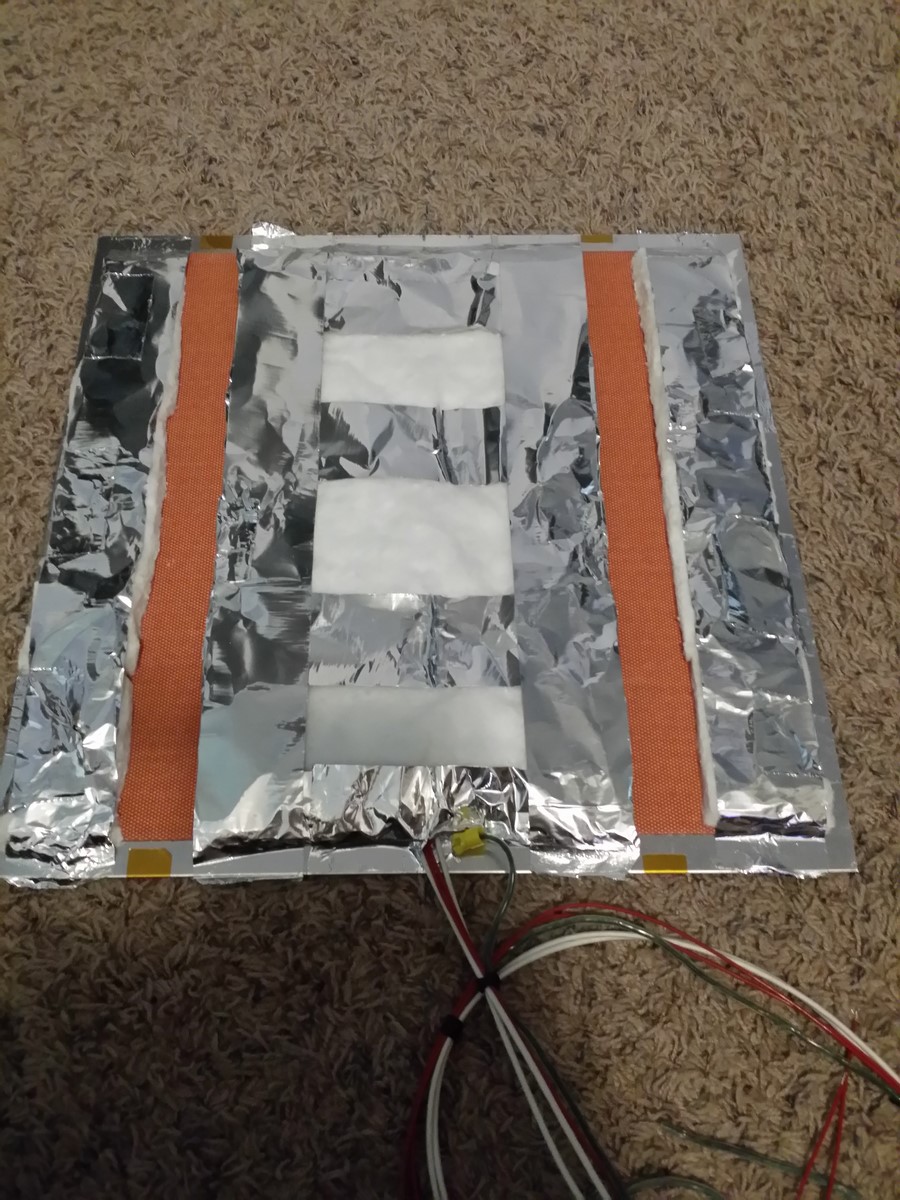
If you are installing any sort of heated build platform:
Use four small pieces of 3/4" tape to mark at the edges exactly where the
build plate sits over the rails in their final positions. Remove the
build plate, and install insulation on the underside without adding any
material or tape in the strips where the build plate rests on its rails. Use
high temperature tapes, adhesives and/or fasteners, without damaging the build
plate or piercing the heater. Return the build plate to the printer, and ensure
that it, its heater, the pressboard strips and the rails are all firmly stacked
with nothing in between them to skew the plate from sitting flat over the
rails.
http://www.neveroddoreven.com/cobblebot/20150822_084802.jpg
http://www.neveroddoreven.com/cobblebot/20150822_090740.jpg
http://www.neveroddoreven.com/cobblebot/20150822_092913.jpg
http://www.neveroddoreven.com/cobblebot/20150822_095354.jpg
You have built the structural and mechanical parts of your printer (more
calibrating to come later).
Re: Building a working Cobblebot gantry
Posted: Sat Aug 15, 2015 2:20 pm
by neveroddoreven
Part 6: Electronics, hotend and extruder
IMPORTANT: Do not energize the 12VDC 30A power supply until instructed!
For ease of assembly, these instructions are currently written for a single
extruder. I'm sure you'll figure out how to add a second one in no time!
You will need:
· 6x M5x8mm low profile screws
· 6x M5 T-nuts
· 2x M3x8mm screws
· 1x M3x10mm screw
· 4x M3x12mm screws (you'll have to buy these -- buy 2x additional if you have a dual hotend)
· 2x M3 nylon lock nuts
· 3x M3 T-nut
· 7x small zip ties
· 5x medium zip ties (5mm wide)
· 1x hotend clip
· 3x mechanical endstops
· 3x endstop extended length cables (not the short ones that come in the bag with the endstops)
· 2x 10mm pieces of solid wire for joining two header pins -- 1/4 watt resistor legs, unused header pin parts, or similar
· 1x Hexagon hotend kit (comes in a plastic box, refer to CB manual)
· 1x extruder kit (comes in a plastic bag, refer to CB manual)
· 1x NEMA17 stepper motor
· 1x extruder motor bracket
· 1x Mega 2560 board
· 1x RAMPS board, and the connectors and jumpers that came with it
· 4x stepper driver motors (either A4988 or DRV8825 will work)
· 1x LCD controller board
· 1x 12VDC 30A power supply
· 1x
switched power cable kit from CB
-or- these two things:
1x common three-wire PC or appliance power supply cable with earth ground
plug/tab, that you can cut one end off
AND 1x dedicated power strip that you can use to switch the printer's mains
power off
· 1x two-conductor insulated 18AWG or better wire, preferably 2 meters but 1 meter works, to run from the elsewhere-located power supply up to the top-mounted RAMPS board (you will need to supply this)
· 1x 2mm ID 4mm OD x 1 meter long PTFE Bowden tube if you have a 1.75mm hotend (or use the CB provided tube if using 3mm hotend)
· 1x piece of roughly 60mm x 130mm thin plywood, pressboard or other insulating plank to mount your Mega board onto
· 1x 40mm x 10mm thick 12VDC fan (a 50mm one would also work)
· Electrical tape
If you have a mains (wall) voltage silicone heater, you will also need:
· 1x solid state relay suitable for 12VDC input and your local mains voltage switched output, and rated at equal or higher wattage load than your heater can draw
· 1x butt crimp connector for 18AWG or better
· 1x circular lug crimp connector for 16AWG or better
· 1x 200mm long two-conductor insulated wire of 18AWG or better
· 1x common three-wire PC or medium-duty appliance power supply cable with earth ground plug/tab, that you can cut one end off
WARNING: Don't jump ahead and connect your RAMPS board to any motors at this
time. We are going to move the motors around by hand a lot in this section,
which causes significant feedback voltages that could fry your electronics
boards.
We are going to rewire your Z motors to run in series from a single connector,
to increase their effective torque without overstressing any components. To
avoid soldering, we will use some sufficiently gauged wire or leftover jumper
pins and electrical tape to join two pairs of wire connectors together. Please
take a look at this series of photos, they explain what's going on more clearly
than what I would express with words. Many backers will find their motor wiring
looms to be of a different color -- that's fine, just follow the wire order on
the connectors. After rewiring, wrap up the two pairs of exposed connectors
securely in electrical, and then wrap them against the whole wiring bundle to
keep from getting tugged apart later. For the curious, the motor pins are
essentially two loops 1A+1B 2A+2B, and flipping the orientation when connecting
to the RAMPS board selects which motor directions will become forward vs
backward motion in the software.
http://www.neveroddoreven.com/cobblebot/20150822_153509.jpg
http://www.neveroddoreven.com/cobblebot/20150822_153931.jpg
http://www.neveroddoreven.com/cobblebot/20150822_154331.jpg
http://www.neveroddoreven.com/cobblebot/20150822_154622.jpg
http://www.neveroddoreven.com/cobblebot/20150822_154818.jpg
http://www.neveroddoreven.com/cobblebot/20150822_154853.jpg
http://www.neveroddoreven.com/cobblebot/20150822_191616.jpg
Prepare your mechanical endstop boards by using wire cutters to trim the excess
through-the-hole tabs from the boards, to reduce them from poking you or
catching on your sleeves. ON ONE ENDSTOP BOARD ONLY, use some pliers to gently
squeeze the metal lever and release it from the switch body -- this will be
your Z endstop.
http://www.neveroddoreven.com/cobblebot/20150822_162101.jpg
http://www.neveroddoreven.com/cobblebot/20150822_162459.jpg
Insert an M3x12mm screw through the center hole in the Z endstop that has its
metal lever removed, with the screw head on the side without any components.
Loosely screw the endstop board (switch button facing UP) against the vertical
rail that has the M3 T-nut already inserted and sitting idle on the wedged
piece of paper. Don't remove the wedged paper in case you drop the screw during
assembly and adjustment. Slide the switch up the rail until it gently strikes
the bottom edge of the Z plate, and ensure you can hear the plate is engaging
the switch upon contact. If not, you will need to find a different mounting
scheme that ensures the switch engages (without the metal lever) and also
protects the endstop pins from shorting out against the frame. Slide the Z
switch back down to the bottom of the rail for now, and tighten until the
endstop board begins to flex and stays firm in its place. NOTE: in a pinch, you
might find that an M3x10mm screw will engage the T-nut about 3/4 of one turn,
but it's not advised as a stable solution and might make future Z home
adjustments painful.
http://www.neveroddoreven.com/cobblebot/20150822_191505.jpg
Insert an M3 T-nut into the Y carriage rail on the face opposite the Y motor
plate, and position it beneath the tall screw that holds the X toothed belt.
Insert an M3x12mm screw through the center hole in one of the remaining endstop
boards, with the screw head on the side without any components, and screw it up
against the T-nut that you just inserted, oriented loosely as shown in the
pictures below. Move the Y carriage so the carriage plate is gently touching
against the X motor and also touching the X motor plate's Z screw. Move the
carriage away from the X motor so that there is 2mm of space between it and the
X motor. This is your Y home position. Without disturbing the Y carriage's
position on the Y rail, gently move the Y endstop switch along on the Y rail
until the arched end-section of its metal lever touches the beveled part of the
Y carriage wheel. The switch should engage without any part of the Y switch
board touching the wheel or the Y carriage. Tighten down the screw until the
endstop board begins to flex and stays firm in its place. Move the Y carriage
away from the X motor toward the non-Z-screw side of the printer, then slowly
bring it back and double-check that the Y endstop switch clicks again just
before it collides into the X motor. Ensure the endstop's board does not touch
the wheel.
http://www.neveroddoreven.com/cobblebot/20150822_195920.jpg
http://www.neveroddoreven.com/cobblebot/20150822_200006.jpg
Engage a small zip tie on itself by just a few clicks to form a nylon loop, and
bend it into the shape as shown in the picture. Verify your remaining endstop
metal solder tabs have been thoroughly trimmed down. Insert an M3x10mm screw
through the center hole, and fasten it to the remaining unoccupied M3 T-nut in
the 551.5mm rail, with nylon loop positioned between the endstop board and the
rail, and the endstop positioned next to the X idler. The nylon loop is acting
as a standoff between the endstop board and the rail. Make sure the Y carriage
is touching its Y endstop switch (Y Home), and then slowly move the Y carriage
towards the X idler until the Y carriage plate gently touches the X idler
plate's Z lead screw. Move the Y carriage away from the lead screw about 2mm.
This is your X home position. Move the X switch into the angle shown in the
photos below, with the beveled part of the wheel touching the middle flat
section of the X endstop metal lever. Ensure the X endstop switch is engaged
without the wheel touching the endstop board, screw the endstop board down, and
test that moving the carriage away and returning it to X home engages the
switch without the wheels hitting anything else, and without the Y carriage
impacting the Z screw.
http://www.neveroddoreven.com/cobblebot/20150822_163430.jpg
http://www.neveroddoreven.com/cobblebot/20150822_171125.jpg
http://www.neveroddoreven.com/cobblebot/20150822_171324.jpg
Completed Minimum X/Y/Z endstop setup:
http://www.neveroddoreven.com/cobblebot/20150822_200044.jpg
Build the Hexagon hotend using the kit and CB manual instructions. Before
threading the brass push-fit part into the heatsink, verify the push-fit can
firmly hang onto and release your PTFE tubing. If you have purchased a push-fit
adapter, remove any rubber seal that it might have come with before installing
it onto the heatsink. Some Hexagon kits come with a thermistor that has slippery
insulation jackets which easily slide away from the glass thermistor, exposing
bare wires that could short easily after assembly. One minor alteration I do
after assembly is to push the thermistor wire insulation jackets fully down to
the glass thermistor bead, and place a small drooping kink in the thermistor
wires on the outside of the silicone boot. This prevents the insulation jackets
from sliding back on the wire later on and causing a wire short inside the
silicone boot or heater block. One other addition I made is to add a single zip
tie that secures the thermistor wires to the heater wires near the hotend.
http://www.neveroddoreven.com/cobblebot/20150822_204504.jpg
http://www.neveroddoreven.com/cobblebot/20150822_210139.jpg
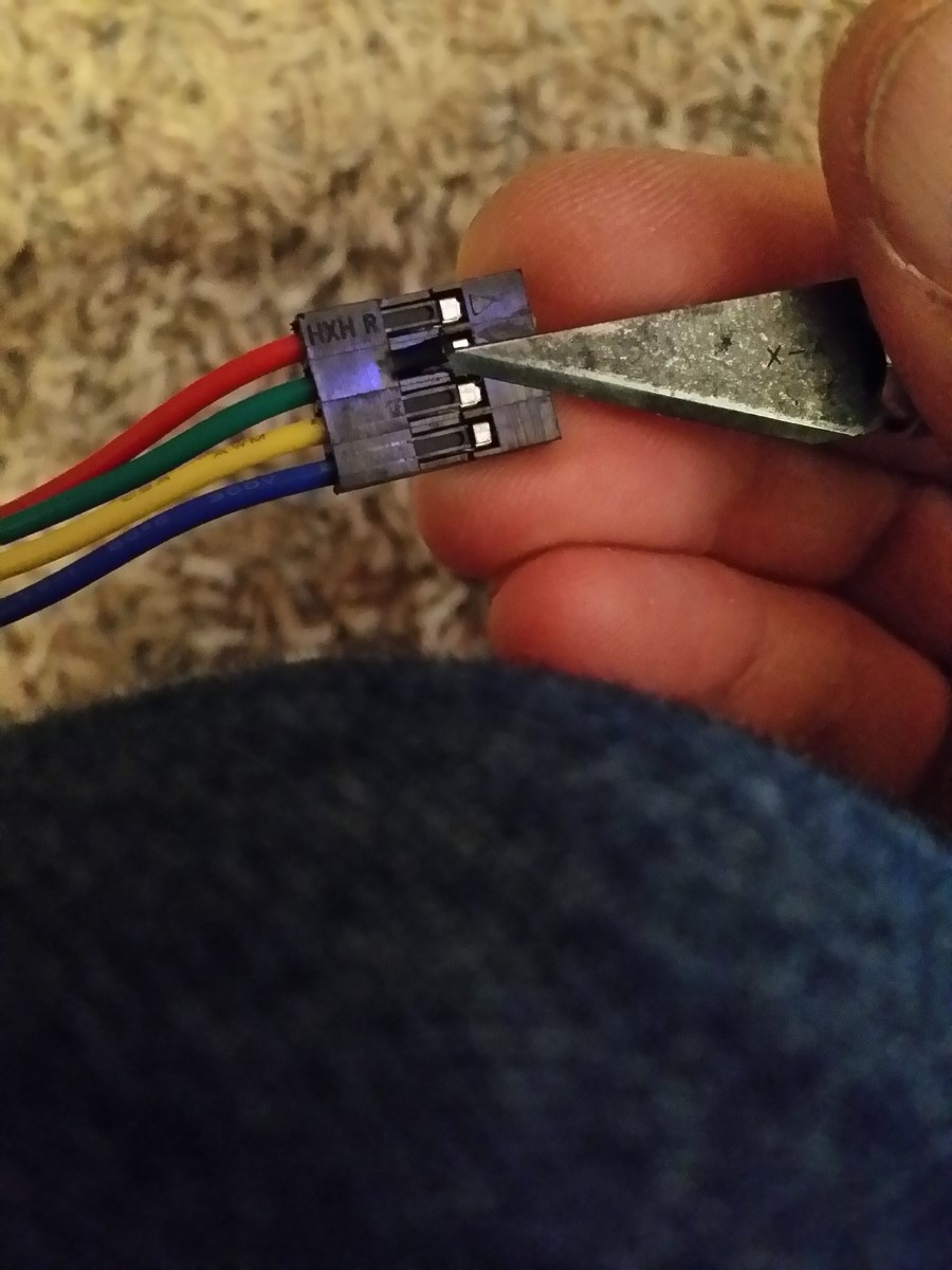
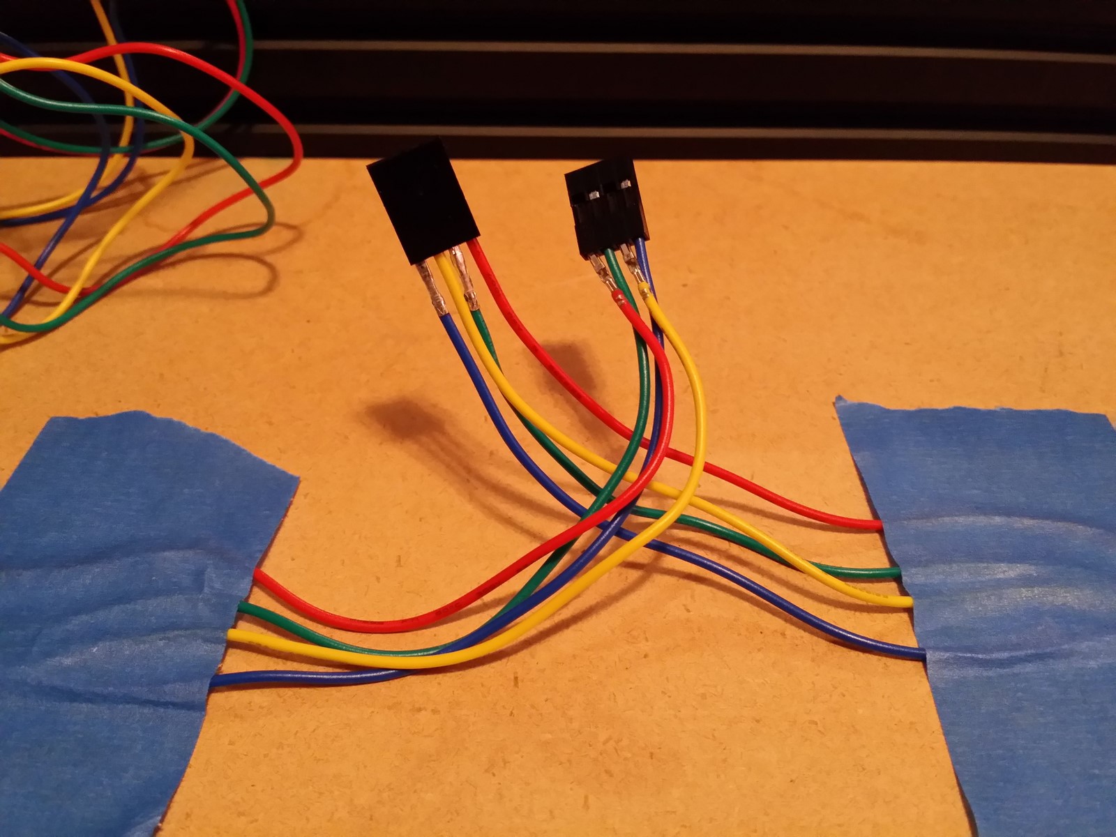
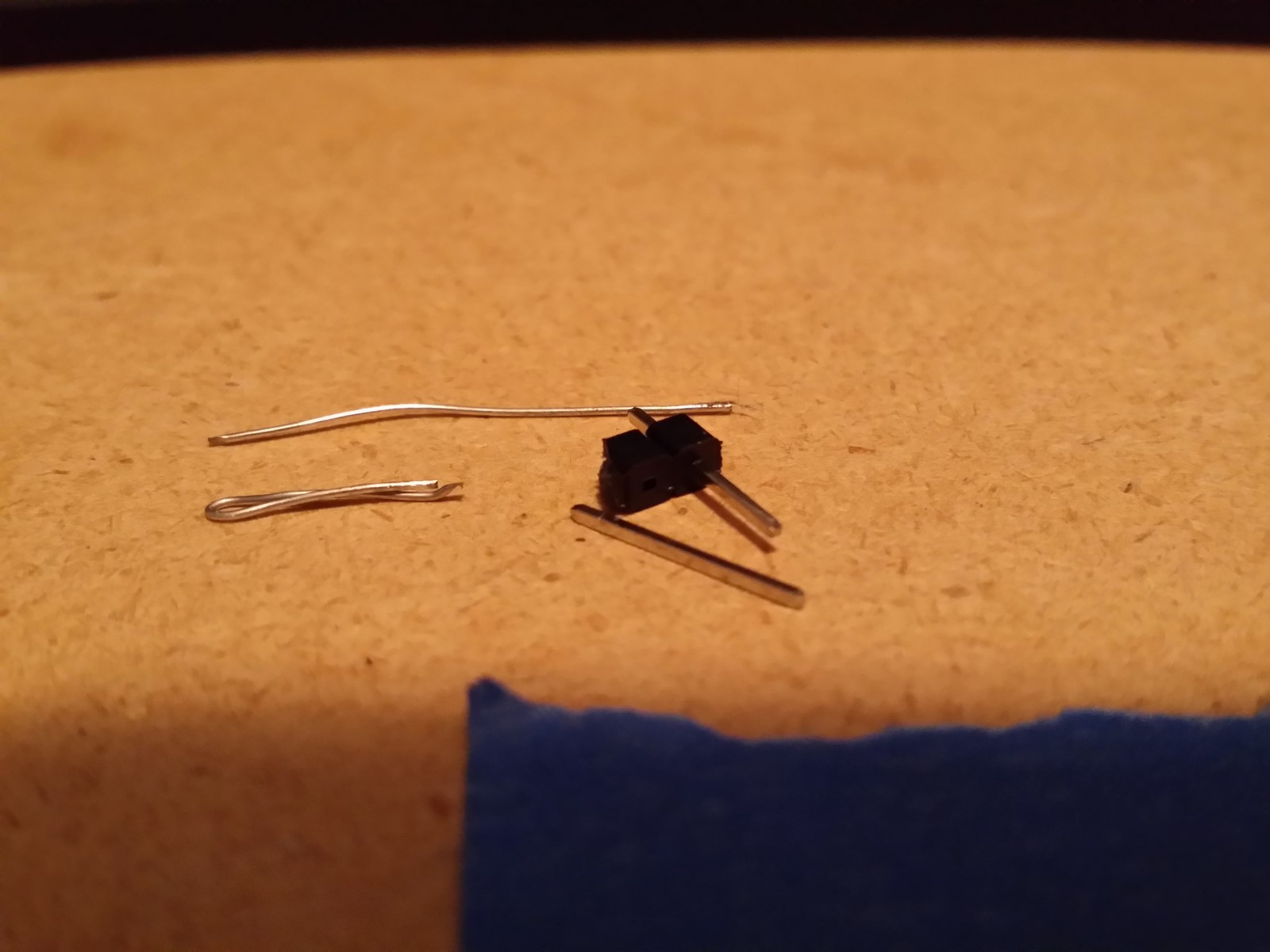
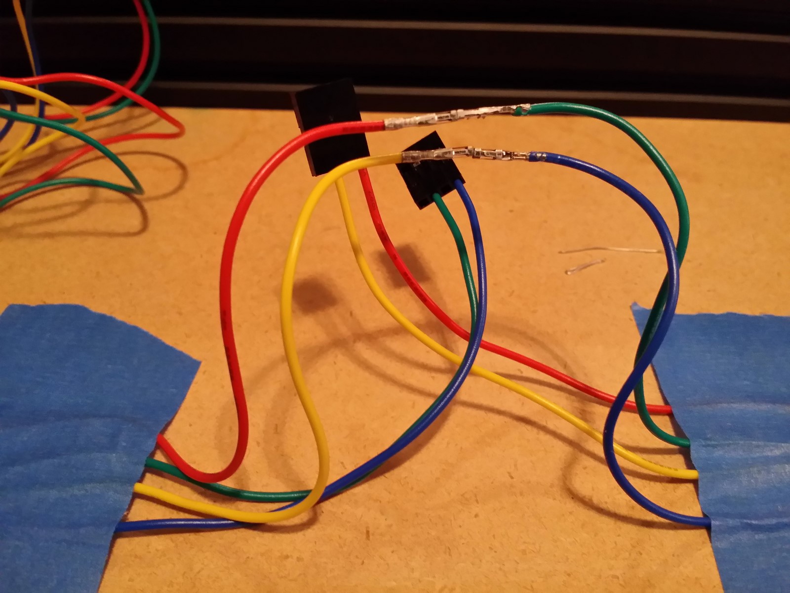
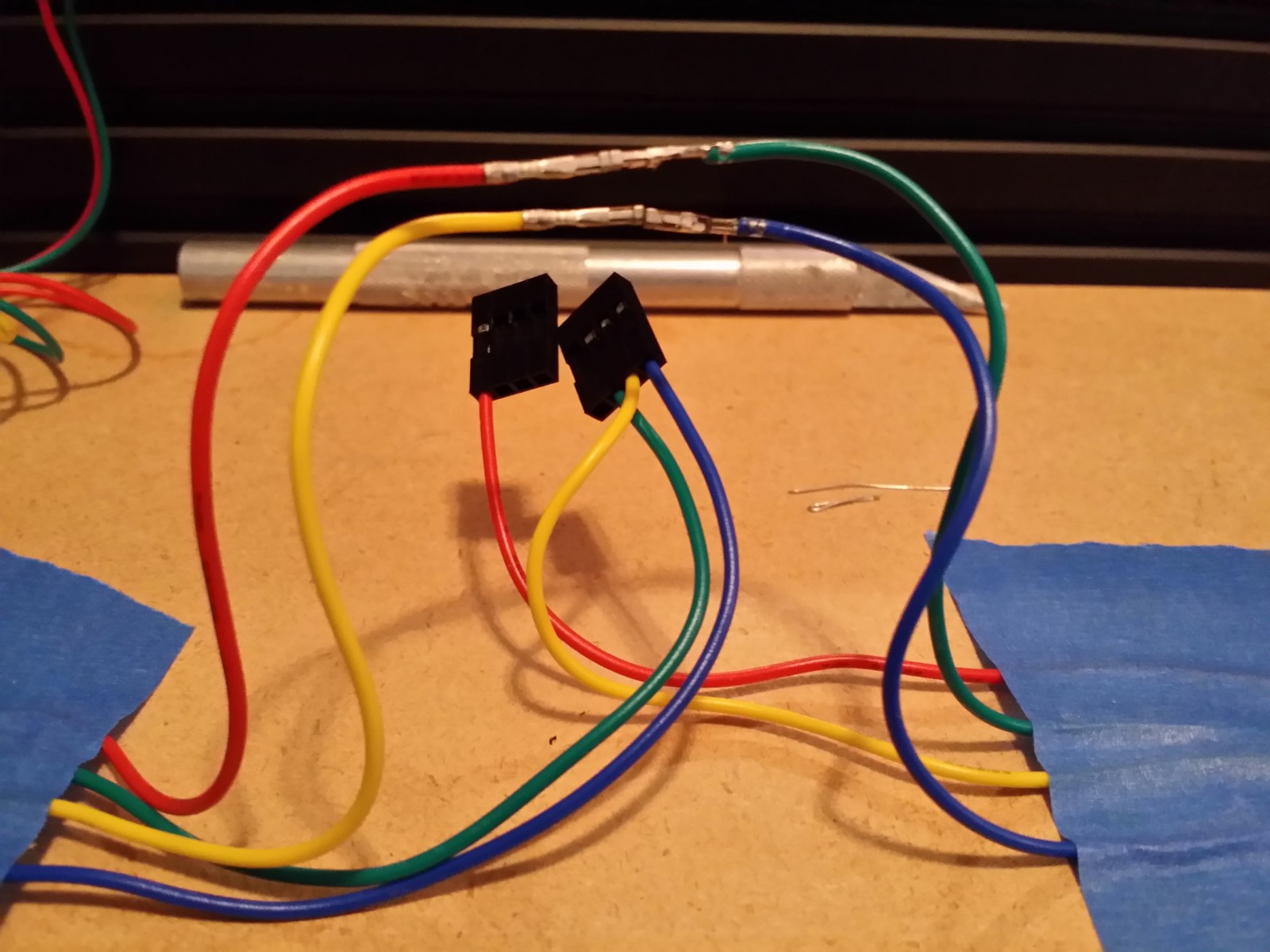
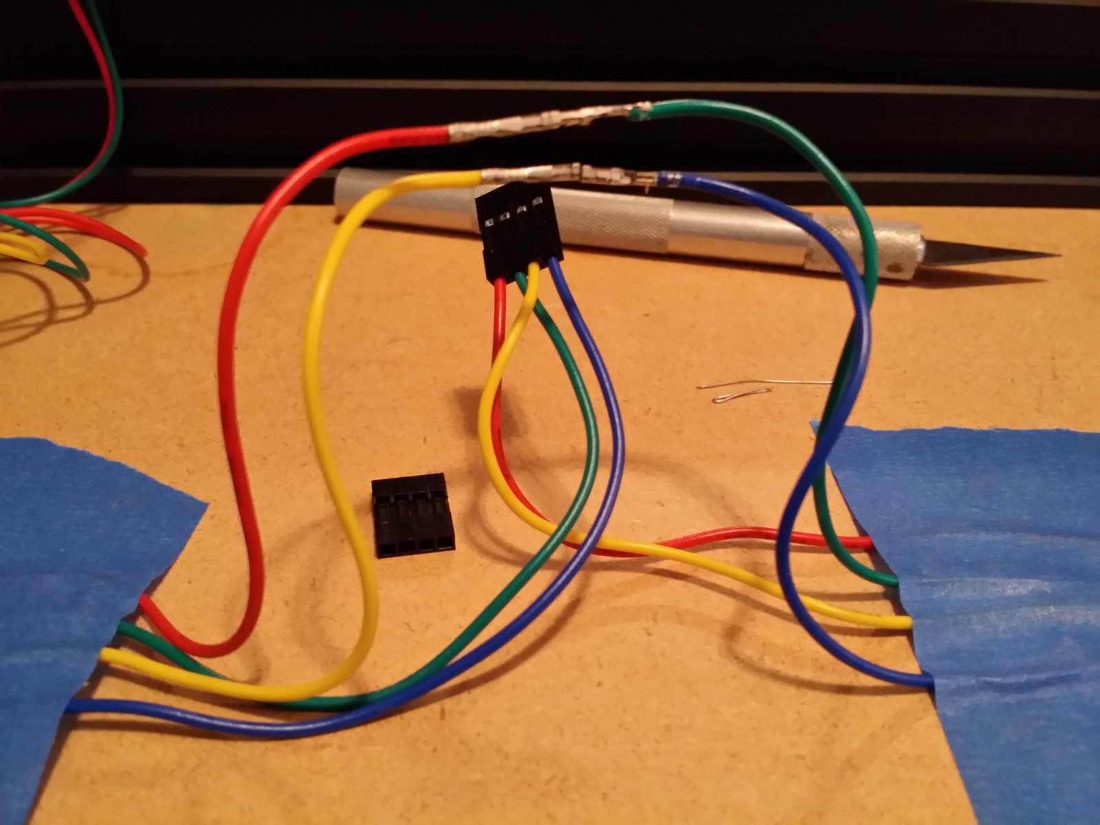
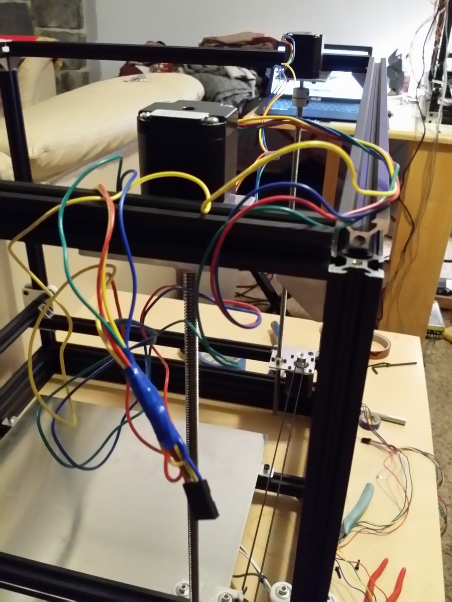
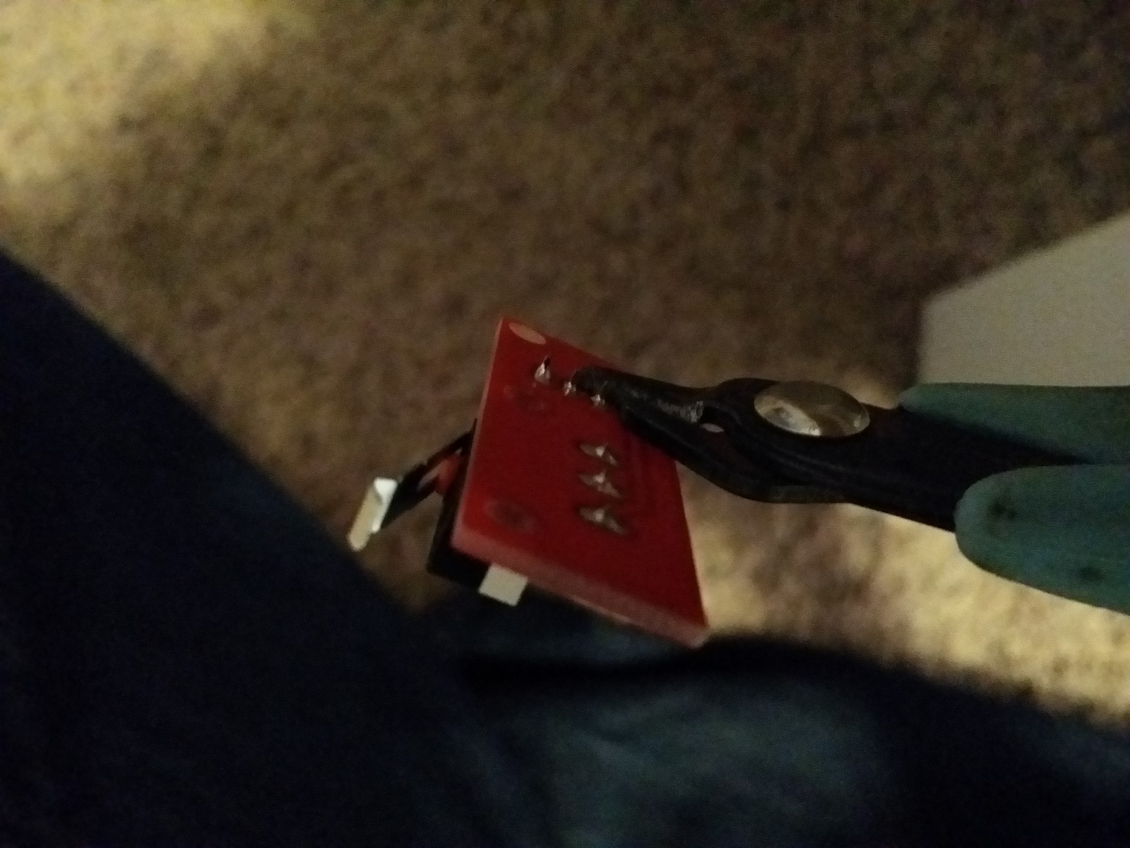
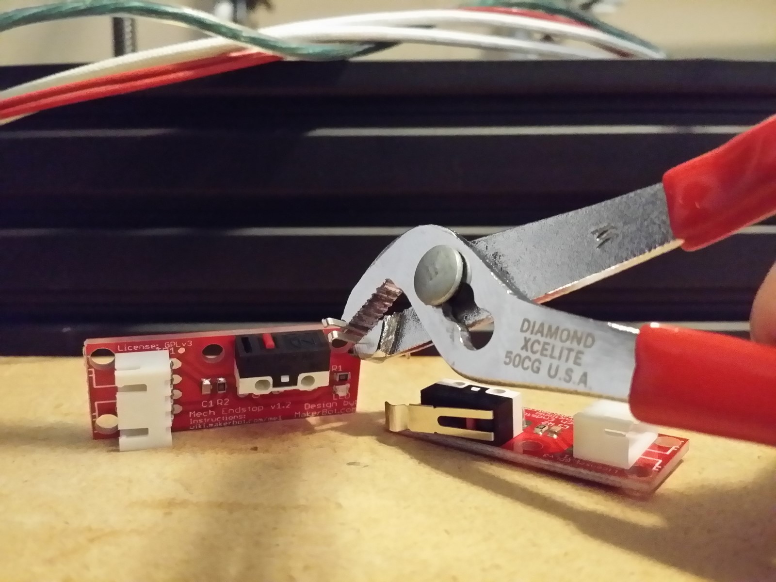
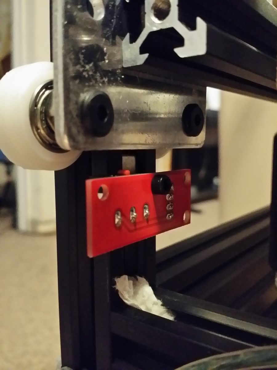
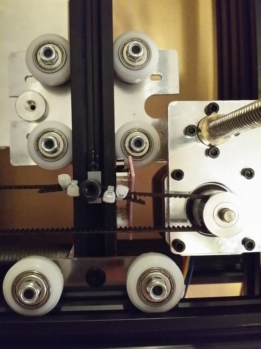
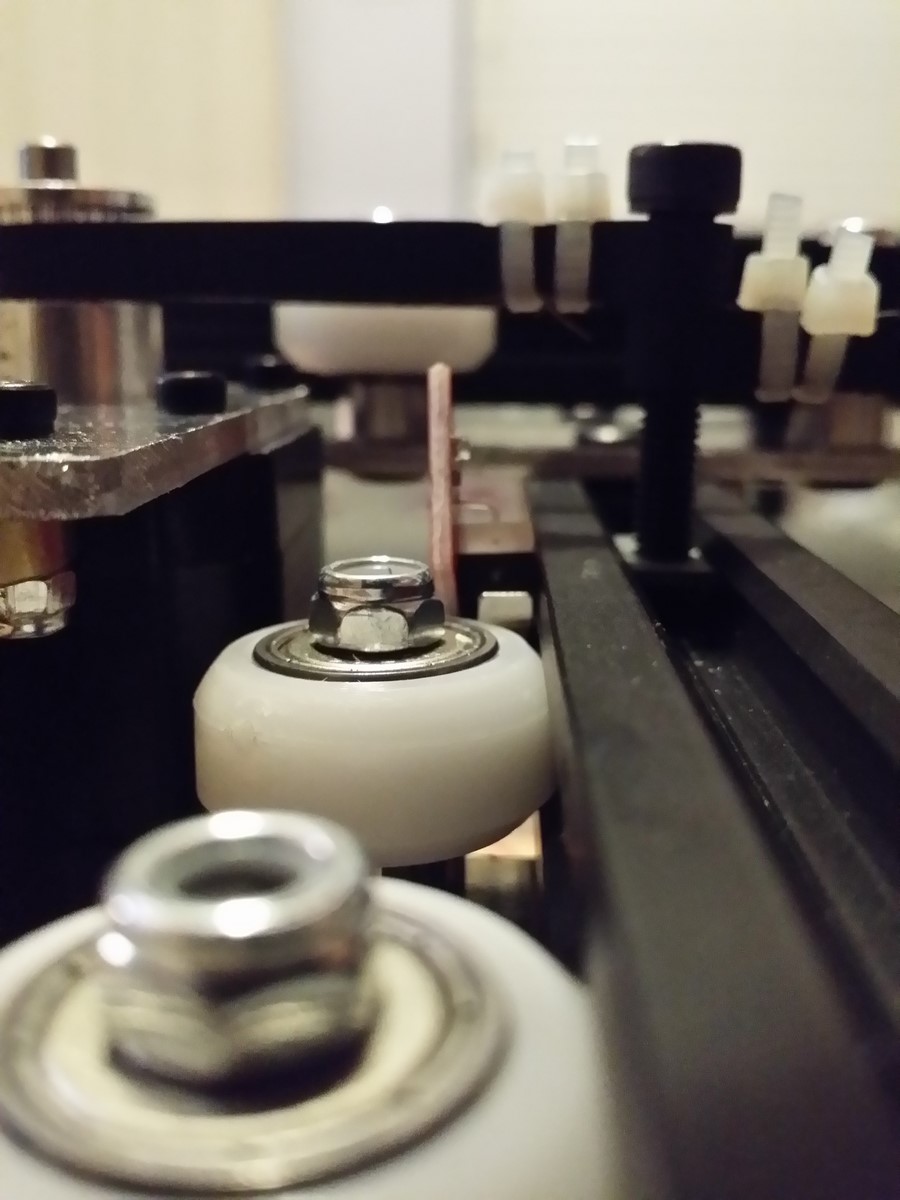
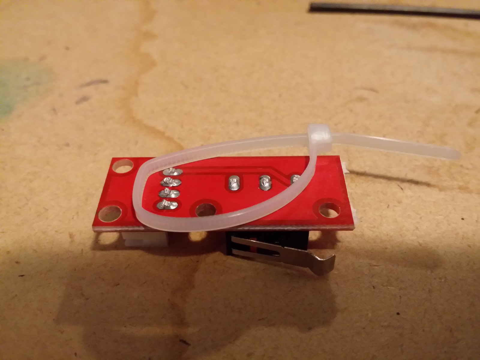
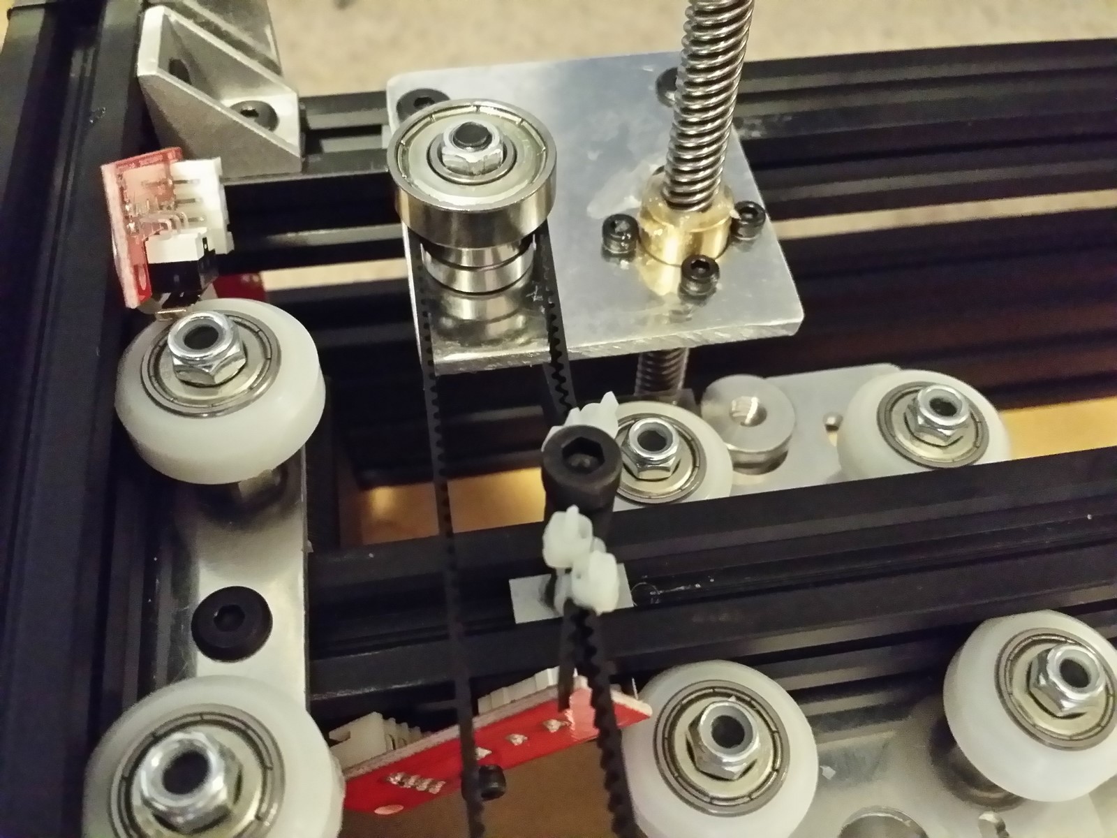
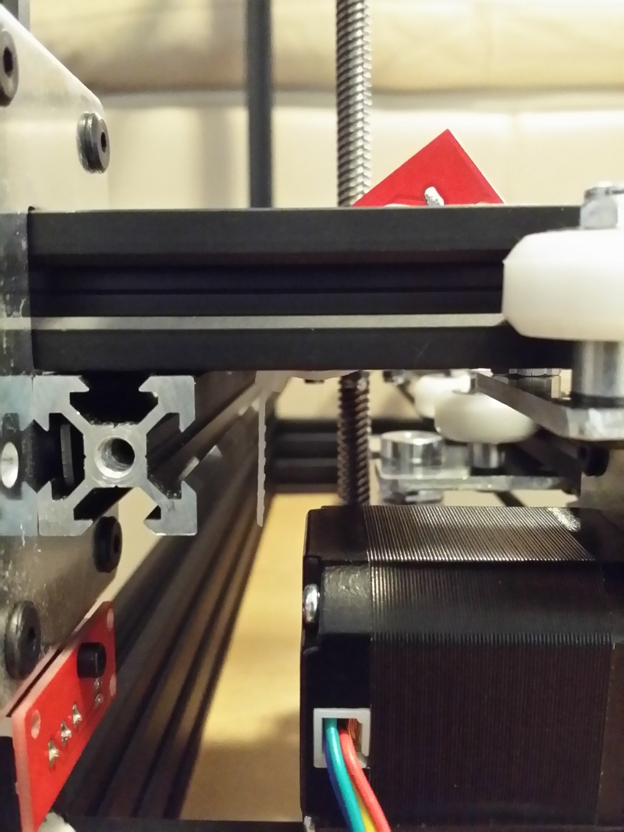
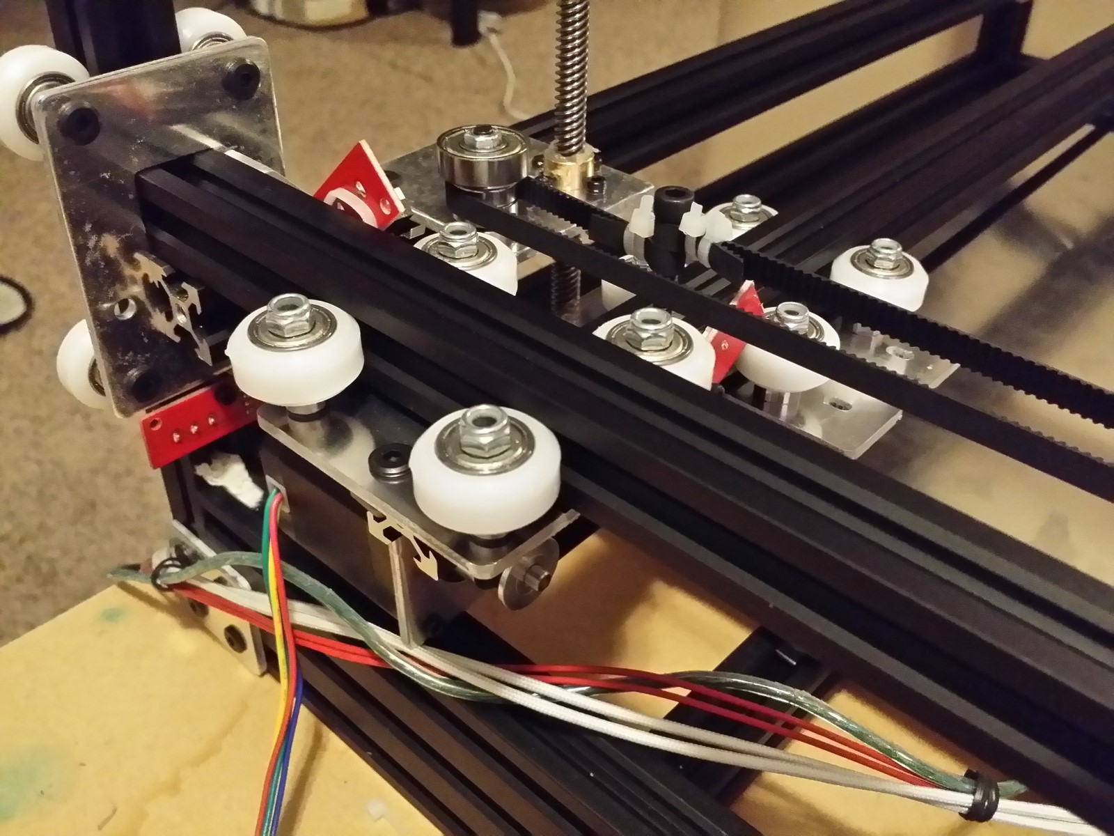
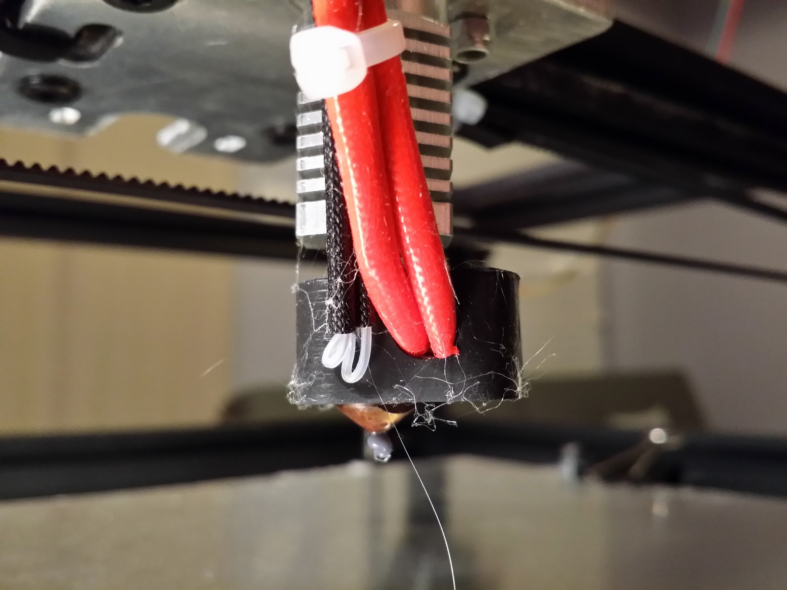
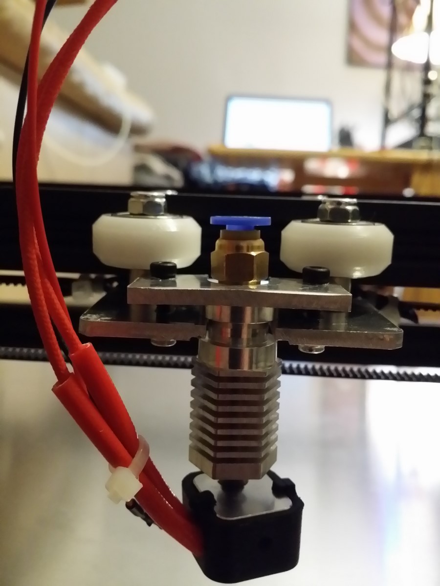
!!OOPS!!
I modeled my Mega board location and wiring choices around my 1B kit's 1 meter
stepper motor wiring harnesses, which are long and plentiful for the task. If
you have a kit with motor wires that are less than 1 meter long (such as some
1A kits), you will need to either modify your wires to be 1 meter long, or you
can modify the instructions on the fly from here. You will instead mount the
Mega board on the 560mm top rail directly over the X motor, and you will
install your X and Z endstops on the opposite rails nearest the X motor.
Unfortunately this means removing the paper wad holding up that M3 T-nut,
letting it fall through under the printer, and then fishing it back up the rail
from underneath on the vertical rail at the opposite side. If you don't want to
recompute these directions on the fly, it might be easier on the brain to just
modify your X and Y motor wires to be 1 meter long. Sorry!
Mount your Mega 2560 board on a small plank of insulating material that can in
turn be mounted to the top rail of your printer. For optimal cable management,
mount the board on the rail directly above the X idler plate, with the Mega
board's USB port pointing away from the X idler and the double-row of board
pins aligned roughly with the center of the nearest Z motor (see pictures). A
cheap suitable solution is pressboard or thin plywood and small zip ties, which
you can later replace with a custom 3D printed case of some sort. Use two
M5x8mm low profile screws and T-nuts, or you might need longer screws depending
on wood thickness. An alternate solution requiring no T-nuts is two pan head M5
8mm screws, upside down and screwed directly into a 11/64" bored hole --
this will slide right into the rail and will stay put if you tighten the screws
into the wood sufficiently. Don't worry about flashing the Mega 2560 for now.
http://www.neveroddoreven.com/cobblebot/20150822_212735.jpg
http://www.neveroddoreven.com/cobblebot/20150822_212752.jpg
http://www.neveroddoreven.com/cobblebot/20150822_215021.jpg
Inspect your RAMPS board for any missing rows of header pins (look around
online for what it's supposed to be populated with). In the off-chance that you
have any missing pins, consult the community and then solder them in now while
it's easy. Install the RAMPS board onto the Mega 2560 board.
http://www.neveroddoreven.com/cobblebot/20150822_213822.jpg
If you have the metal LCD mounting bracket, mount the LCD onto the bracket, and
then mount the bracket vertically on the other side of the corner where the
Mega board is mounted. You will need four 16mm M3 screws and plain nuts (not
provided) to hold the LCD to the plate, or perhaps you can use small zip ties.
http://www.neveroddoreven.com/cobblebot/20150823_090846.jpg
If you do not have the metal LCD mounting bracket, a temporary solution is to
use kapton tape with the thick bubble foam sheet that your RAMPS board came
with, and tape the LCD to the corner of your frame until you are able to print
out a proper LCD plate or other LCD housing. It is important to do this
reasonably soon, as there are many sensitive pins on the back of the LED that
can damage your Mega board if they were to accidentally be shorted to the rail
or to each other. Do not press too hard on the rotary encoder, or place it
against the rail because its solder pins might punch through the bubble foam
and touch the rail. Attach the LCD to the RAMPS board using its included header
adapter.
http://www.neveroddoreven.com/cobblebot/20150822_220822.jpg
--LINK TO LCD PLATE STL, ANYONE?--
Slide two M3 T-nuts into the interior face of the same top rail that you
mounted the LCD plate against. Using the T-nuts and two M3x8mm screws, mount
the extruder bracket to the middle of the same rail that the LCD plate is
mounted against, with the round stepper motor hole oriented horizontally and
above the rail. If you plan to build two extruders, you'll want to mount both
brackets at this time and leave about 10mm of space between them.
http://www.neveroddoreven.com/cobblebot/20150823_081045.jpg
Follow the CB manual instructions to build the extruder directly onto the
mounted extruder bracket using the NEMA17 stepper motor and the extruder kit.
Orient your extruder so the lever is facing outside the printer and the brass
quick-fit fitting points toward the center of the printer. If you try to first
build the extruder in the bracket and then mount the bracket, it will be tough
to thread and tighten the M3 screws holding it to the rail. After assembling,
tighten the lever depth set screw (the longest one in the kit) just until the
extruder bearing is barely not touching against the extruder gear, and the gear
can turn without turning the bearing.
http://www.neveroddoreven.com/cobblebot/20150823_083132.jpg
If you received a switched mains power cable from CB:
You're all set. Move along.
If you are making your own mains power cable for your printer's power supply:
Remove the PC/appliance end of the mains power cable you are using. Carefully
strip 4mm of insulation from all three conductors without nicking or cutting
off a bunch of the wire strands. Groom and twist the wire strands neatly for
testing and insertion in the next few sets of steps.
http://www.neveroddoreven.com/cobblebot/20150823_102647.jpg
WITHOUT PLUGGING YOUR MAINS POWER CABLE INTO THE WALL, use an ohm meter to
verify which wire goes to the mains live prong (USA: usually black), which wire
goes to the mains neutral prong (USA: usually white), and which wire goes to
the mains earth ground prong (USA: usually green). Write these down for use
later. If you have a CB-provided switched power cord, you will need to test the
end of the cable with the spade connectors, because the colors change on the
other side of the power switch.
https://en.wikipedia.org/wiki/AC_power_plugs_and_sockets
Examine your CB-provided power supply by shaking it moderately. If you hear a
loud rattle, it is defective. At their own risk, a few users have attempted to
repair the rattle defect using some instructions posted by another user:
viewtopic.php?f=4&t=1620&p=11168#p11168
On the side of the CB-provided power supply, there is an small opening with a
switch inside for setting the supply input voltage to 110 or 220 volt. Set this
appropriately for your local mains voltage. Failure to do this will probably
fry your power supply.
Attach the mains power cable to the CB-provided power supply. The lug terminals
are labeled "L" for live, "N" for neutral and " ⏚ "
for earth ground (if you can't see the character, look up "earth ground
character"). If you are using a self-prepared cable, ensure your ends stay
neat and unfrayed, and bend them into an arc so they go clockwise around the
lug screw as you insert them (you don't want the wire poking out of the side of
the lug terminal). Tighten firmly, but don't overtighten or you might begin to
cut into the wire strands.
http://www.neveroddoreven.com/cobblebot/20150823_103239.jpg
http://www.neveroddoreven.com/cobblebot/20150823_103627.jpg
Ensure the CB power supply is not connected to anything besides its own power
cable, with a physical switch (either the CB inline switch, or through a dedicated
power strip switch). Locate a small green LED inside the power supply just
behind the right-most lug terminal marked "+V". Turn the switch to
the off position, and plug the power cable into the wall. Turn the switch on
and immediately inspect for the green LED to light up. If it does not light,
your power supply is defective. A few users, at their own risk, have referred
to the defective power supply thread link mentioned earlier above.
http://www.neveroddoreven.com/cobblebot/20150823_105215.jpg
Unplug the CB power supply cable so it cannot receive any mains power. We won't
energize it again for awhile.
If you are using a mains powered silicone bed heater:
Mount your solid state relay (which should have come on a heatsink) on the same
rail as the Mega board, with the 12VDC input side facing toward the Mega board,
and spaced about 150mm away to give ample room for yanking out the Mega USB
cable in an emergency.
http://www.neveroddoreven.com/cobblebot/20150823_084708.jpg
Prepare your dedicated mains power cable for the heater using the same
instructions above for self-preparing a CB power supply mains cable, and also
identify the live/neutral/ground wires as you did earlier for your CB power
supply cable. Attach the bed heater mains cable's live (but not actually live!)
wire to one of the load terminals on the SSR. Route all of the bed heater wires
out of the printer on the side where the SSR is, and attach one of the bed
heater line voltage wires to the other load terminal on the SSR. Use a butt
crimp connector to connect the bed heater mains cable's neutral wire directly
to the other bed heater line voltage wire. Use a circular lug crimp connector
and an M5x8mm screw to connect both the bed heater mains cable's ground wire
and the bed ground wire to one of the nearest rail ends, in order to ground the
whole printer frame and the bed to earth.
http://www.neveroddoreven.com/cobblebot/20150823_114635.jpg
Using a 200mm two-conductor insulated 18AWG or better wire, connect the
negative and positive input terminals of the SSR to the negative and positive
outputs of the "D8" heated bed terminals on the RAMPS board.
http://www.neveroddoreven.com/cobblebot/20150823_185342.jpg
Install a two-conductor header connector on the ends of the heated bed
thermistor wires. It must be exactly two conductors wide because it will plug
into the middle pins of a six-pin header array. If you don't have crimp/solder
header connectors on hand, you can cannibalize a prewired connector from some
useless part you have lying around, and then crimp/solder the connector wires
onto the heated bed thermistor wires. For example, you could cannibalize one of
the unused too-short three-wire cables that were packed with the endstops, and
use heavy wire cutters to carefully chop the connector down to exactly two
conductors wide. Install the thermistor connector onto the RAMPS board T1
header, pin orientation doesn't matter for simple thermistors.
http://www.neveroddoreven.com/cobblebot/20150823_192302.jpg
Stepper driver jumper choices are quite the topic in the 3D printer community.
We will select these stepper driver jumper settings for the following reasons.
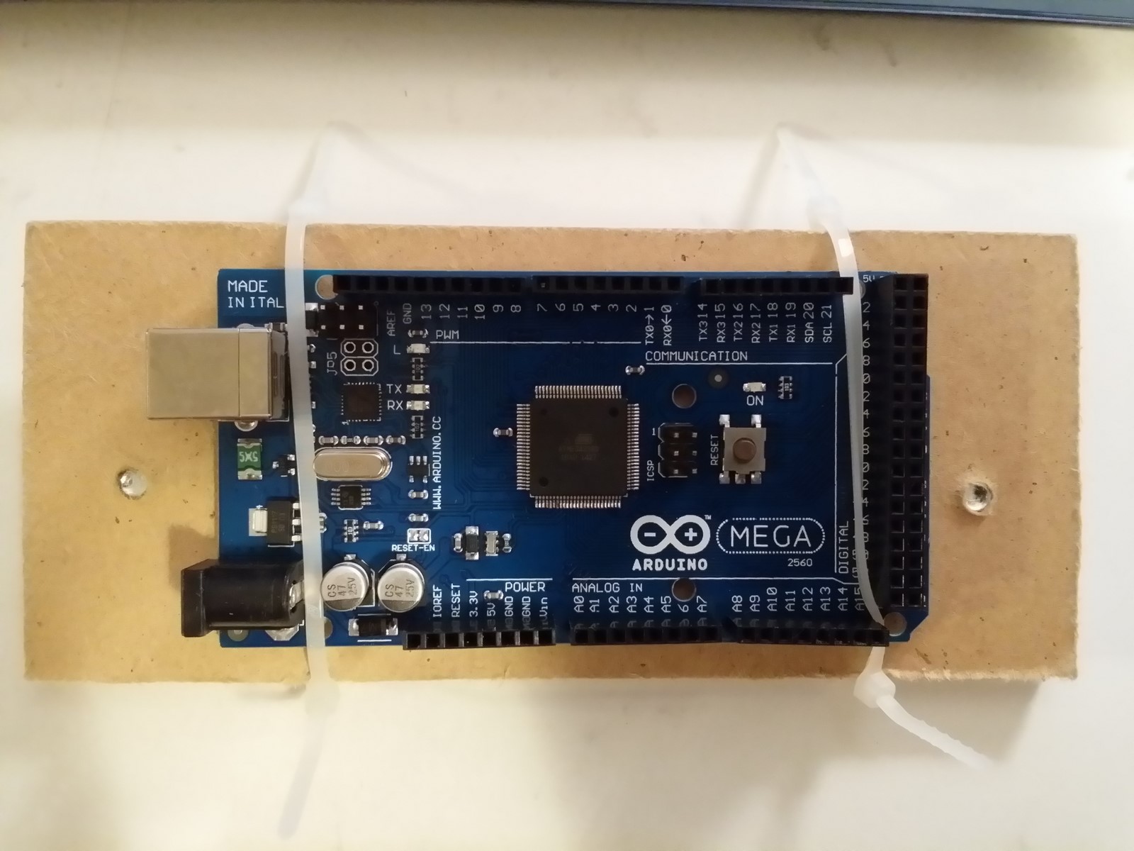
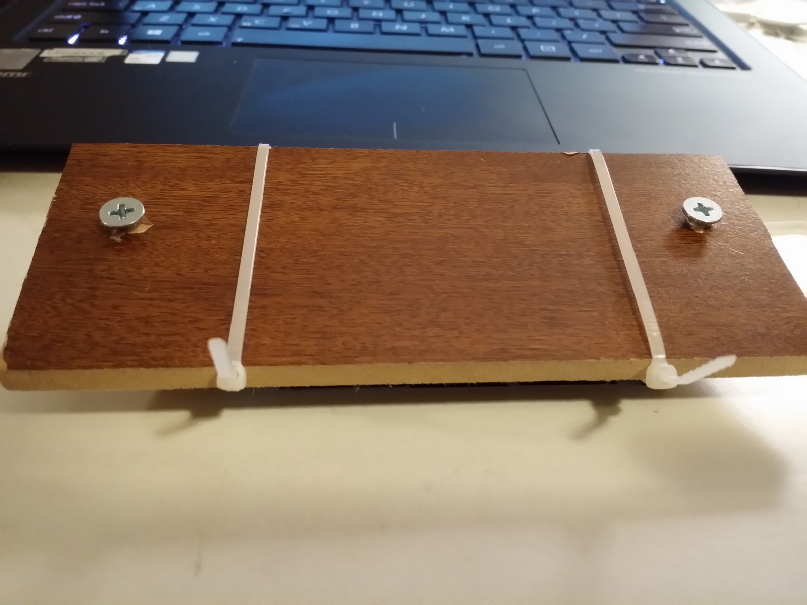
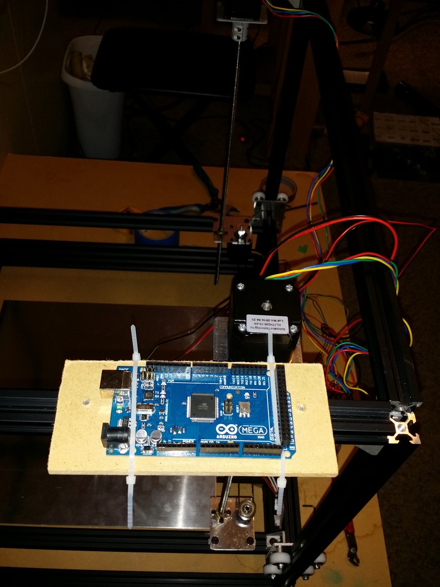
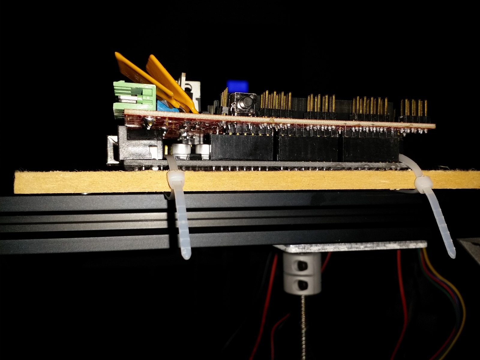
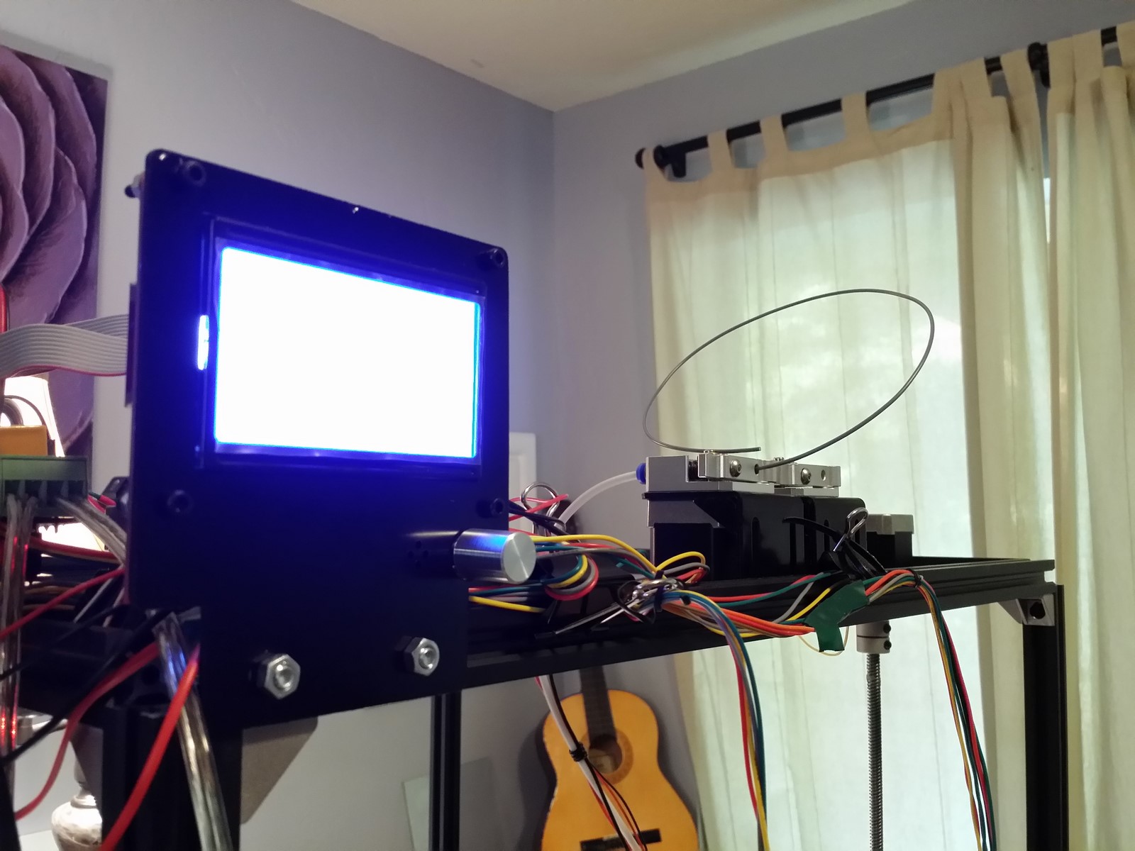
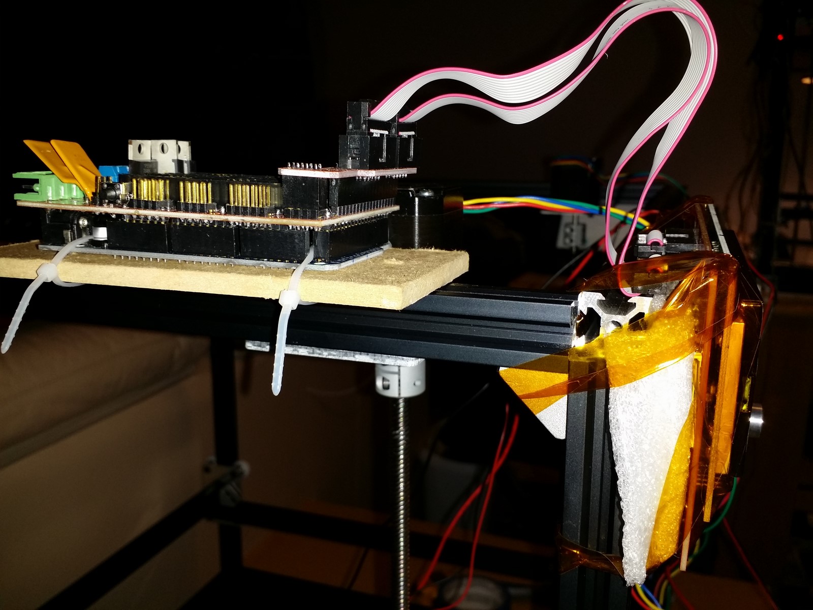
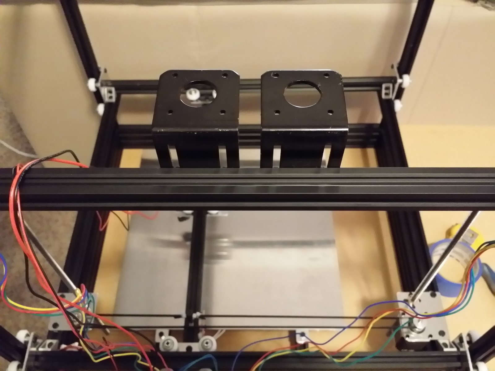
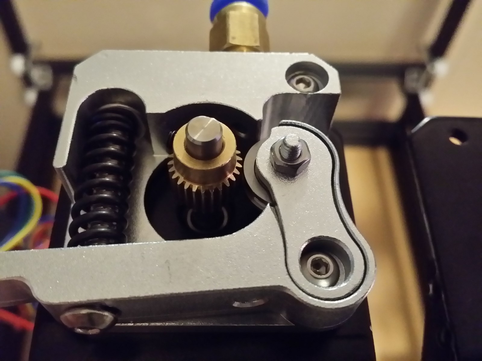
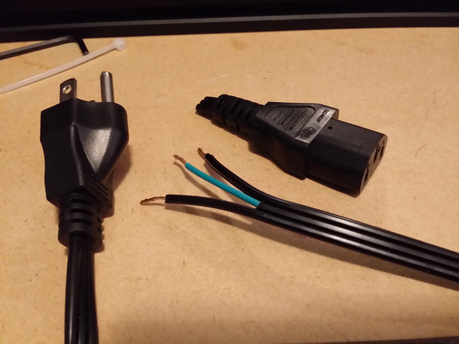
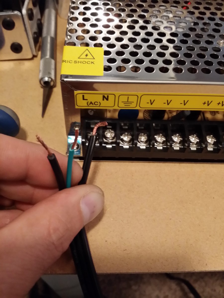
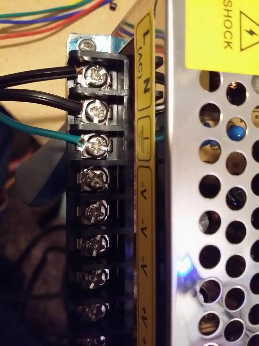
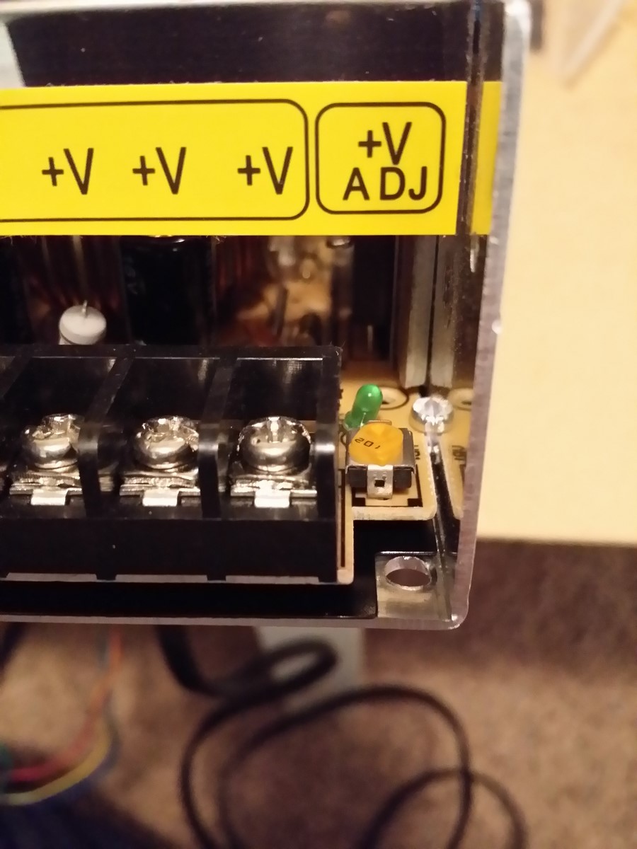
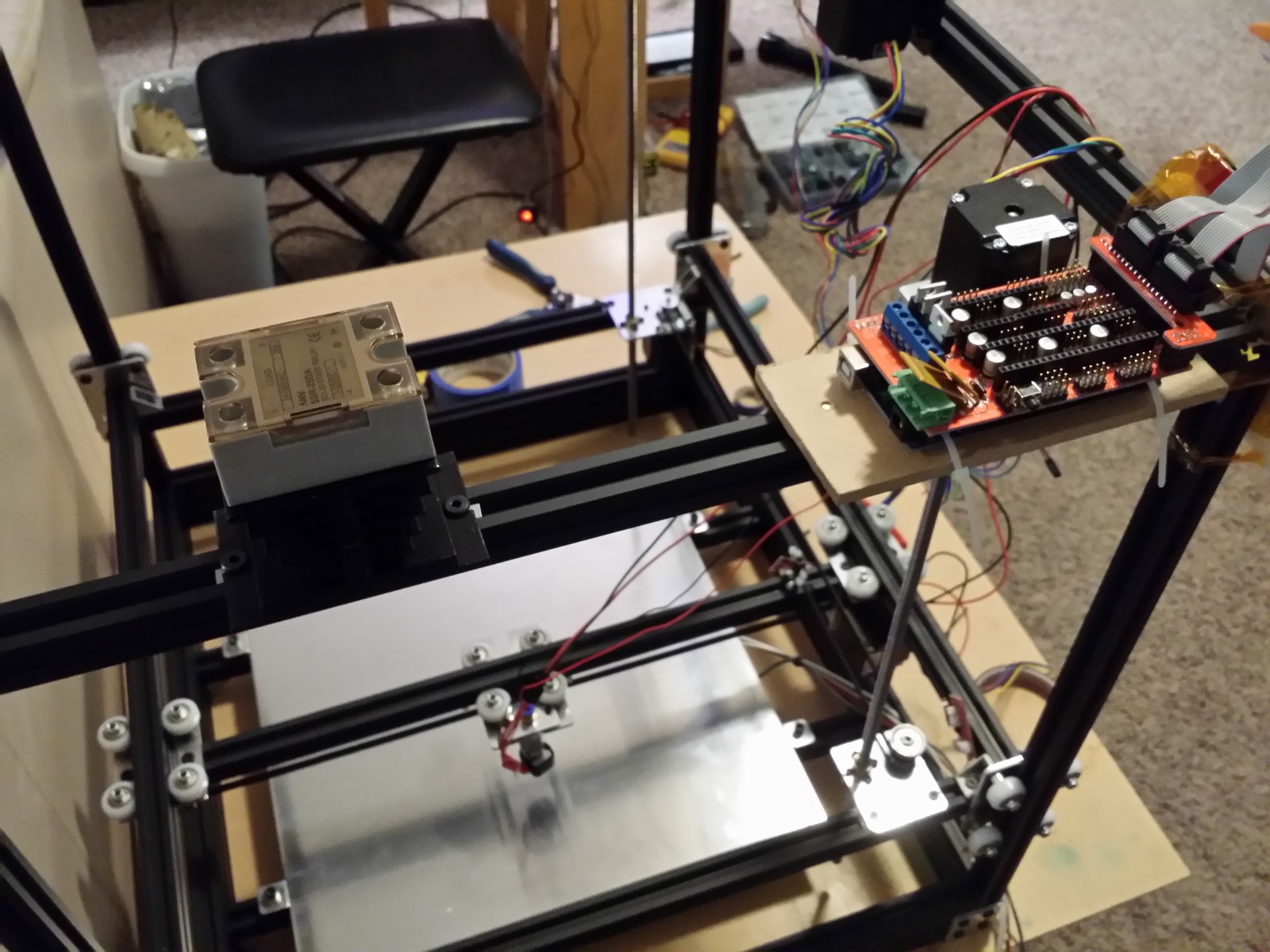
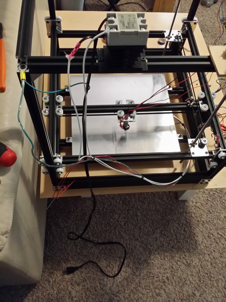
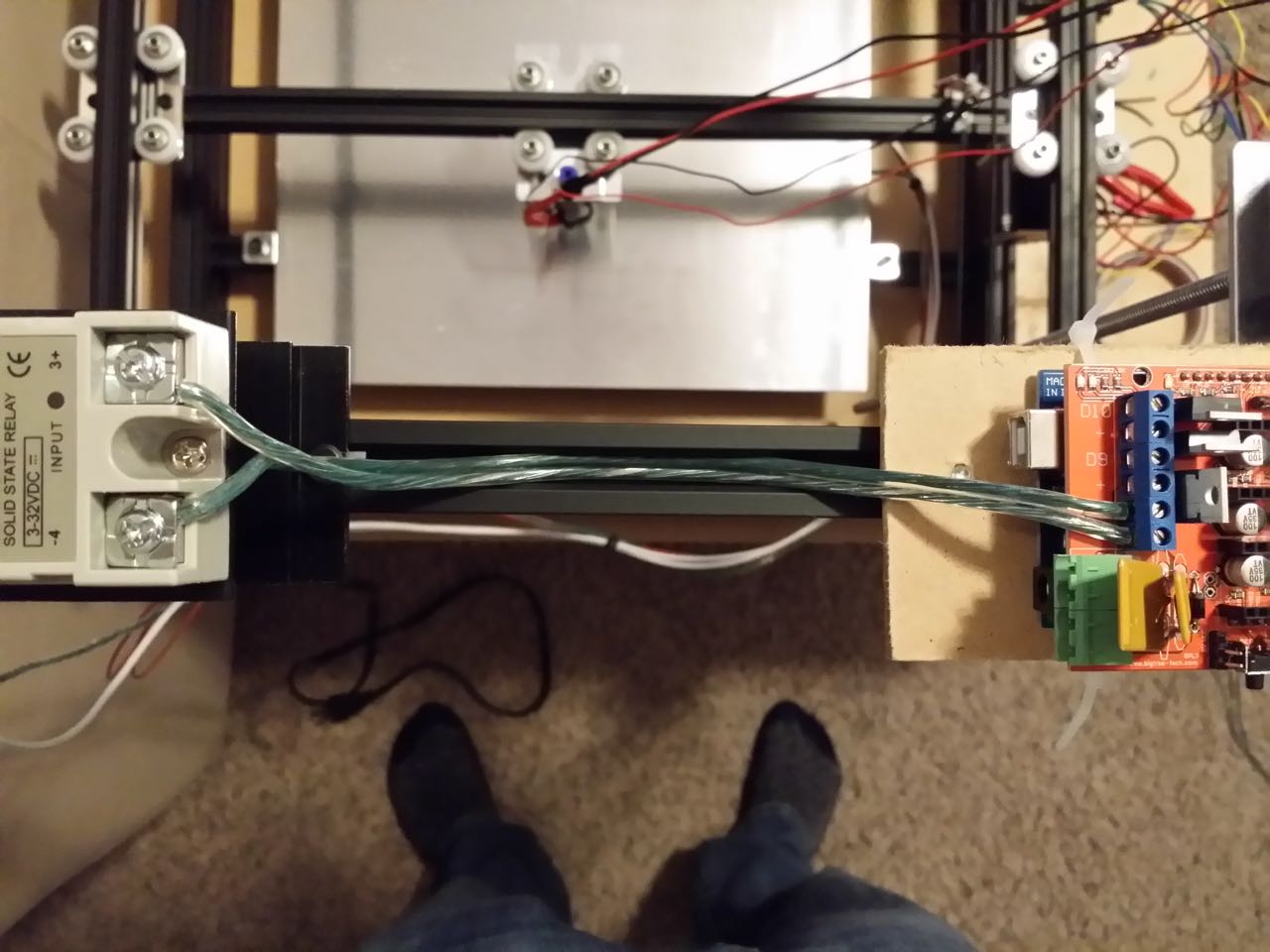
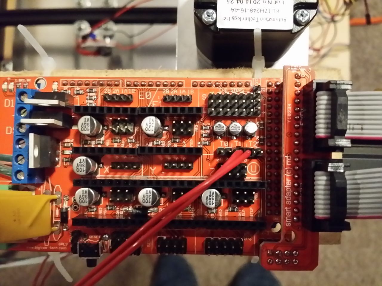
· X and Y:
Highest available resolution (1/16 on A4988, 1/32 on DRV8825)
Most precise axes on a Cartesian printer, matters greatly when doing things
like arcs.
· Z: 1/16
step resolution
On this lead screw 1/16 steps comes out to 95.5 steps/mm, aka 0.01mm resolution,
easily capable of dealing with 0.1mm layer heights, and still allows on the fly
software bed leveling without overtaxing the Mega 2560.
· E: 1/16
step resolution
This is about as much resolution as a direct-drive Bowden-fed hotend can
actually realize, without demanding too high of a step rate from the Mega chip
during rapid retraction moves.
Below are some images that demonstrate the jumper settings chosen
above, along with a temporary example of a correctly oriented stepper driver in
the unused secondary extruder socket (just duplicate the first extruder jumper
settings if you have two of them).
Install your stepper motor jumpers, and install the stepper drivers in the
correct orientation. If you are unsure, examine the stepper board for pin labels
and match them up with pin labels on the RAMPS board. Installing the stepper
board in the wrong orientation is almost certain to fry it upon initial
power-up.
A4988:
http://www.neveroddoreven.com/cobblebot/20150823_201854.jpg
DRV8825 (two DRV8825 model examples):
http://www.neveroddoreven.com/cobblebot/20150823_201549.jpg
http://www.neveroddoreven.com/cobblebot/20150823_201612.jpg
Jumper settings described here:
http://www.geeetech.com/wiki/index.php/Ramps1.4
Locate the two green screw-down quick connectors that were supplied together
with the RAMPS board. Insert these two connectors into the green plugs on the
RAMPS board, and examine the board markings behind the plugs (you might need to
bend the yellow capacitors away to see). Verify which terminals are positive
and which terminals are negative. Connect the two >1meter long 18AWG or
greater two-conductor cables to the green connectors, paying special attention
to which conductors you are wiring as the positive or negative conductors.
Attach the two positive wires to any two positive terminals on the CB power
supply, then attach the remaining two negative wires. Double check everything
for correct polarity -- if wrong you will almost certainly fry most of your
electronics. Also double check that there are no frayed wire ends sticking out
of the connectors or CB power supply terminals. Unplug the green connectors
from the RAMPS board for safety while we continue building
http://www.neveroddoreven.com/cobblebot/20150823_203606.jpg
Attach the X endstop's wiring harness, route it out of the X-idler side of the
printer and up to where the Mega board is, and plug it into the X-Min header on
the RAMPS board, with the (usually red) 5V wire facing toward the center of the
RAMPS board. The endstop headers are six rows of three-pin headers, X-Min /
X-Max / Y-Min / Y-Max / Z-Min / Z-Max, and after Z-Max you will find a four-pin
I2C header.
http://www.neveroddoreven.com/cobblebot/20150824_190436.jpg
You will need three 200mm or longer wires of at least 22AWG to extend the Y
endstop wiring harness. You might be able to salvage enough from the wires that
came packed with the endstops. In some cases with another 3-wire cable already
having header connectors on both ends, you might not need to cut, strip and
solder/twist any wires if you can use leftover header pins or twist-tie wire to
join the (perhaps disassembled) connectors together. You are aiming to get at
least 900mm of cable for the Y endstop.
Attach the Y endstop's wiring harness, and route it away from the Y rail and up
toward the middle of the top-mounted extruder above. Pin it in place using a
bulldog clip, route the cable over and connect it to the Y-Min header on the
RAMPS board.
http://www.neveroddoreven.com/cobblebot/20150824_191946.jpg
http://www.neveroddoreven.com/cobblebot/20150824_192014.jpg
http://www.neveroddoreven.com/cobblebot/20150824_192037.jpg
Attach the Z endstop's wiring harness, route it out of the X-idler side of the
printer and up to the Mega board, and plug it into the Z-Min header.
http://www.neveroddoreven.com/cobblebot/20150824_192225.jpg
http://www.neveroddoreven.com/cobblebot/20150824_192247.jpg
Ensure the nozzle is raised at least 5mm from the build plate. Inspect your
PTFE Bowden tube and decide which end is cut the cleanest and most
perpendicular to the tube (aka square). If you don't have a clean square cut
end, use a hobby knife (and probably a few attempts) to make one end really
square and clean, without using up too much tubing in the process. Insert the
clean square-cut PTFE Bowden tube end down into the Hexagon quick-fit and push
it in firmly until it stops, about 8 to 10mm. Move the Y carriage to the
furthest corner away from the X-idler, and lower the nozzle until it is nearly
touching the build plate. Find the shortest distance that your Bowden tube can
reach up to your extruder's brass fitting without bending significantly at
either end, add 20mm, and trim your tube to that length. I trimmed the Bowden
tube to a conservative total length of 745mm, and I will probably trim off
another 25mm in the future after printing for around 50 hours (there is no
un-trimming!). Insert the now-trimmed Bowden cable into the extruder brass
fitting and seat it firmly.
http://www.neveroddoreven.com/cobblebot/20150824_195714.jpg
Bundle the hotend cables with the Bowden tube and wrap twist ties around it at
regular intervals up to about 100mm from the extruder brass fitting. Plug the
hotend thermistor wire into the RAMPS board T0 header, pin orientation doesn't
matter for simple thermistors. Groom and twist the thicker hotend heater wires,
and insert them into the D10 screw-down terminals on the RAMPS board
(positive/negative doesn't matter for these resistive heaters). Screw the D10
terminals down firmly.
http://www.neveroddoreven.com/cobblebot/20150825_181305.jpg
WARNING!
From this point forward, you should only move your printer gantry by hand under
the following conditions:
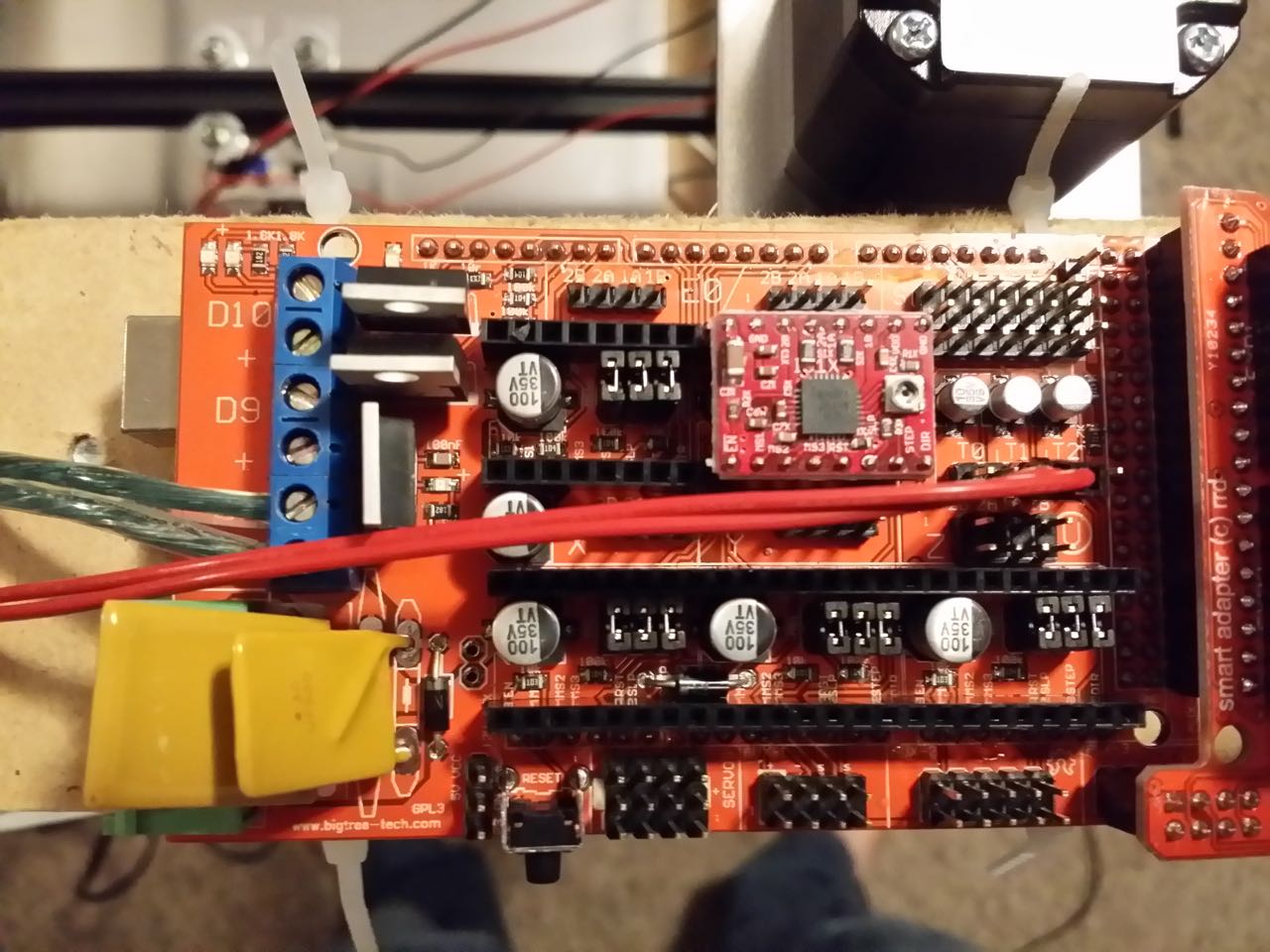
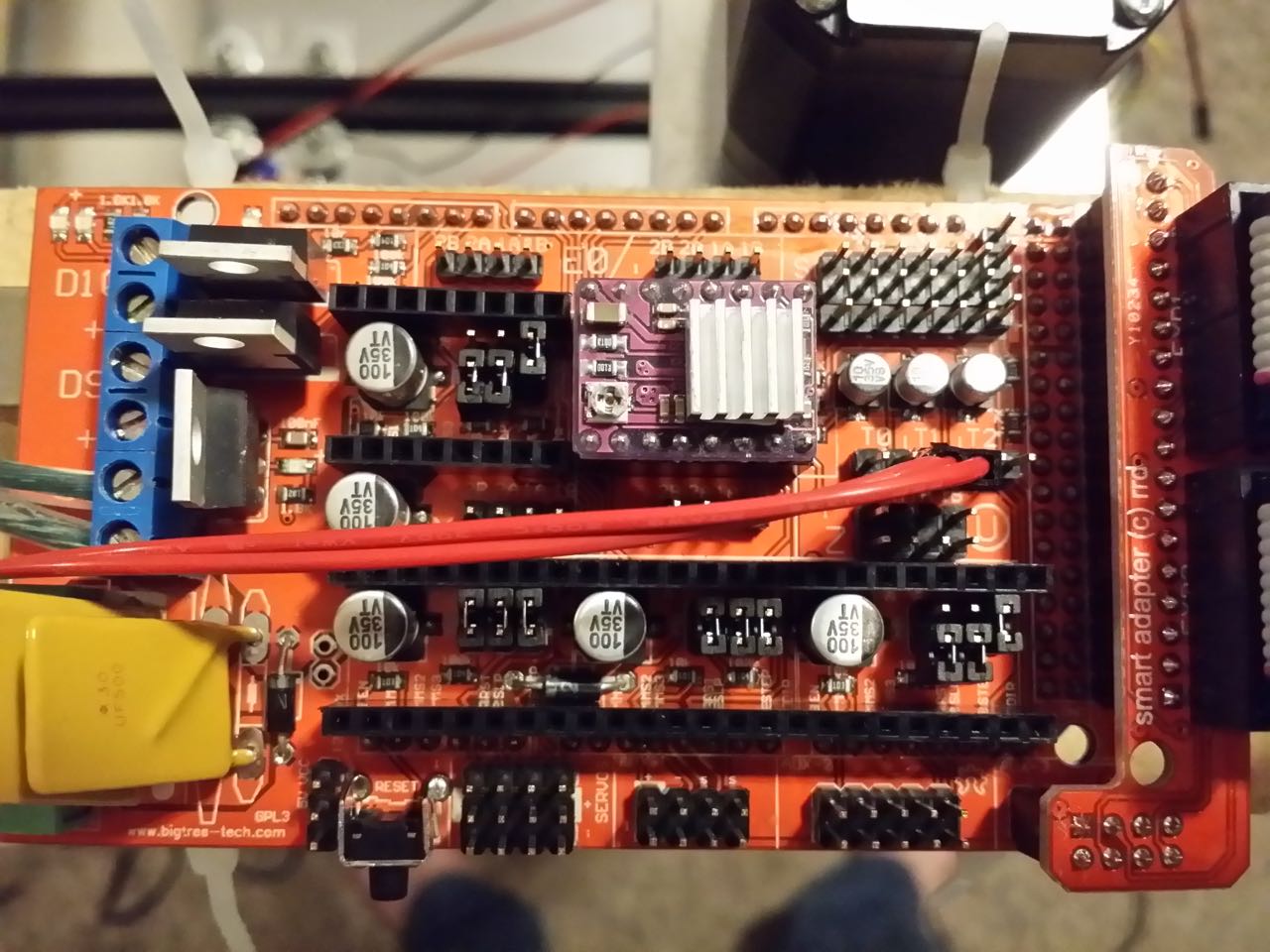
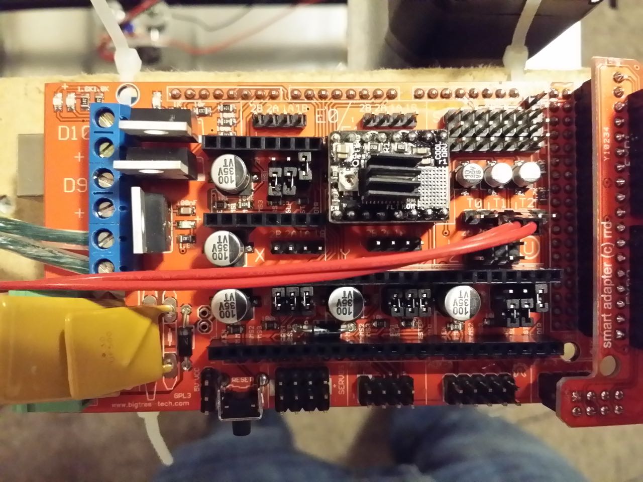
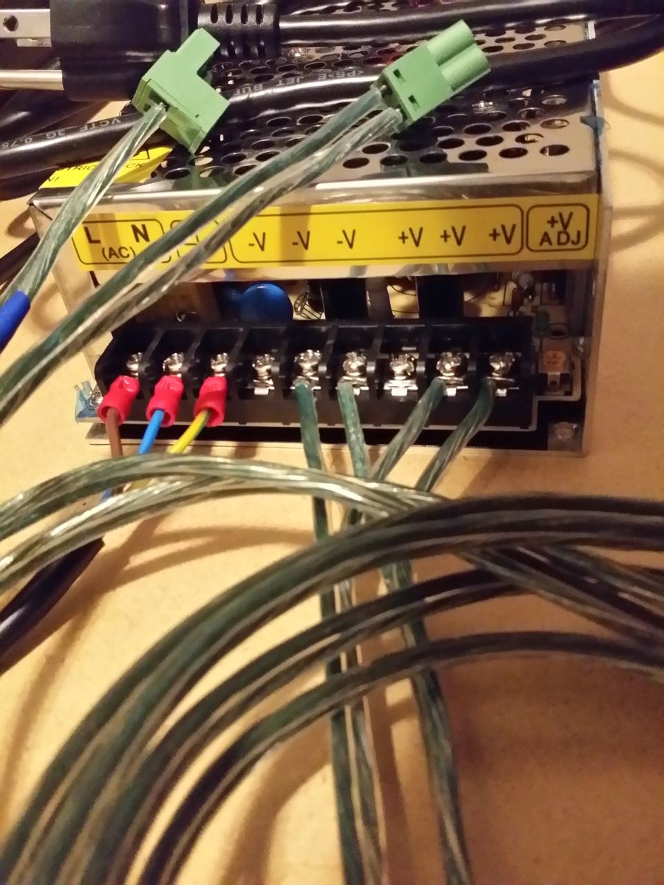
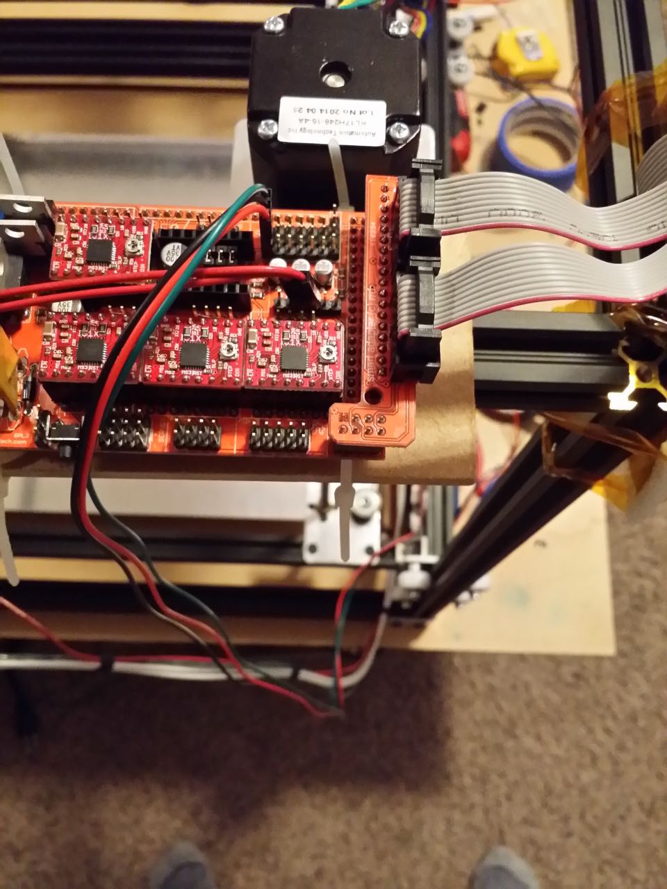
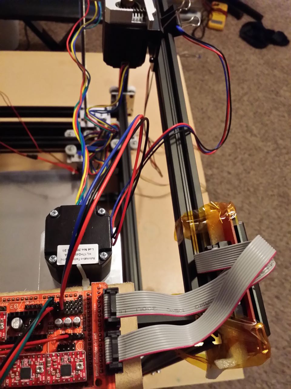
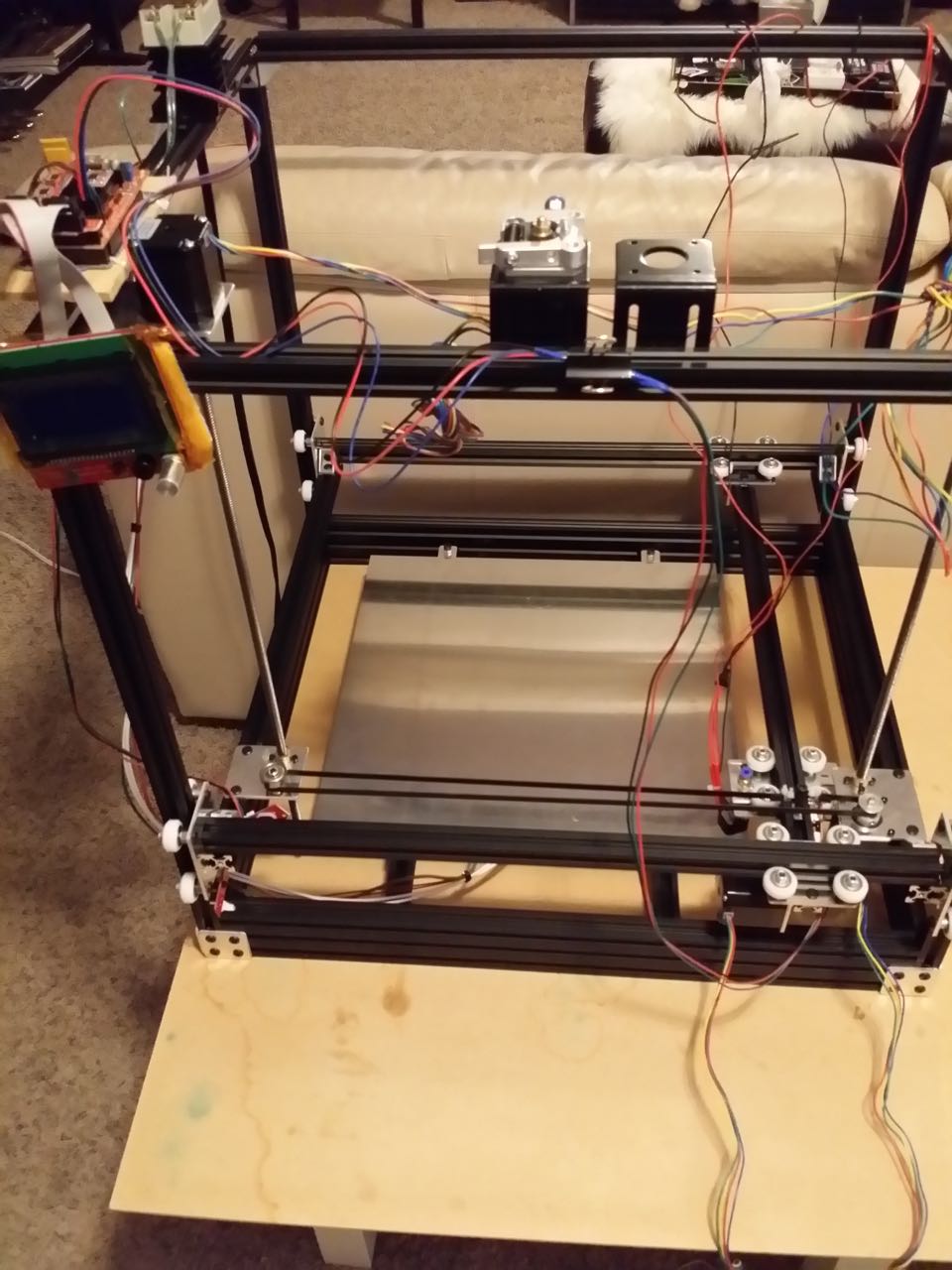
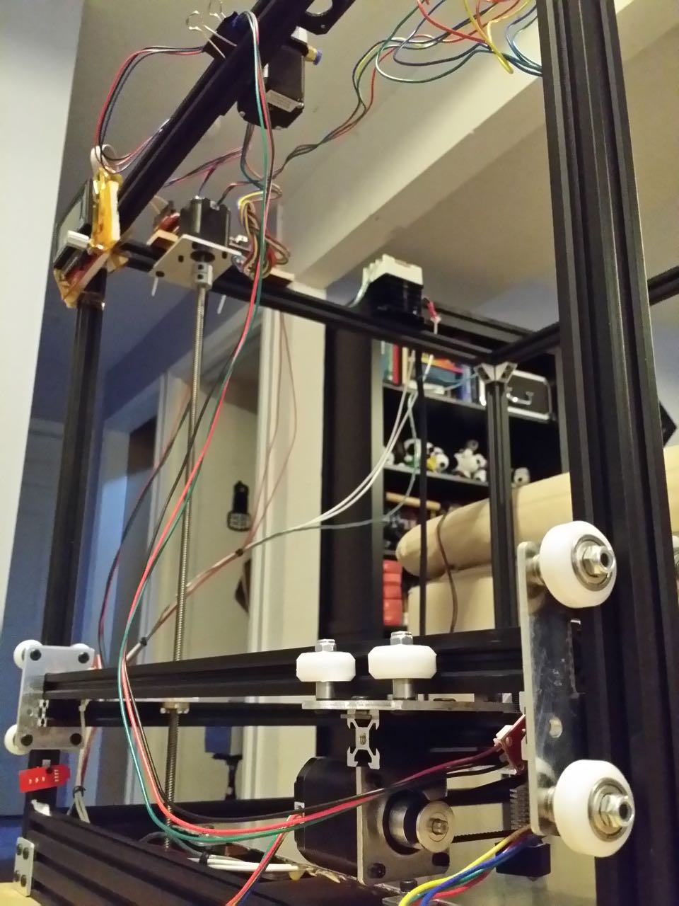
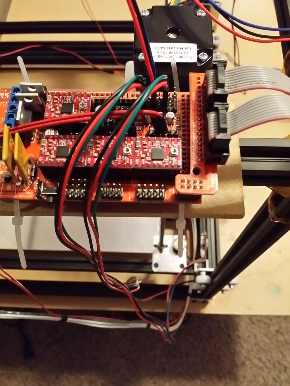
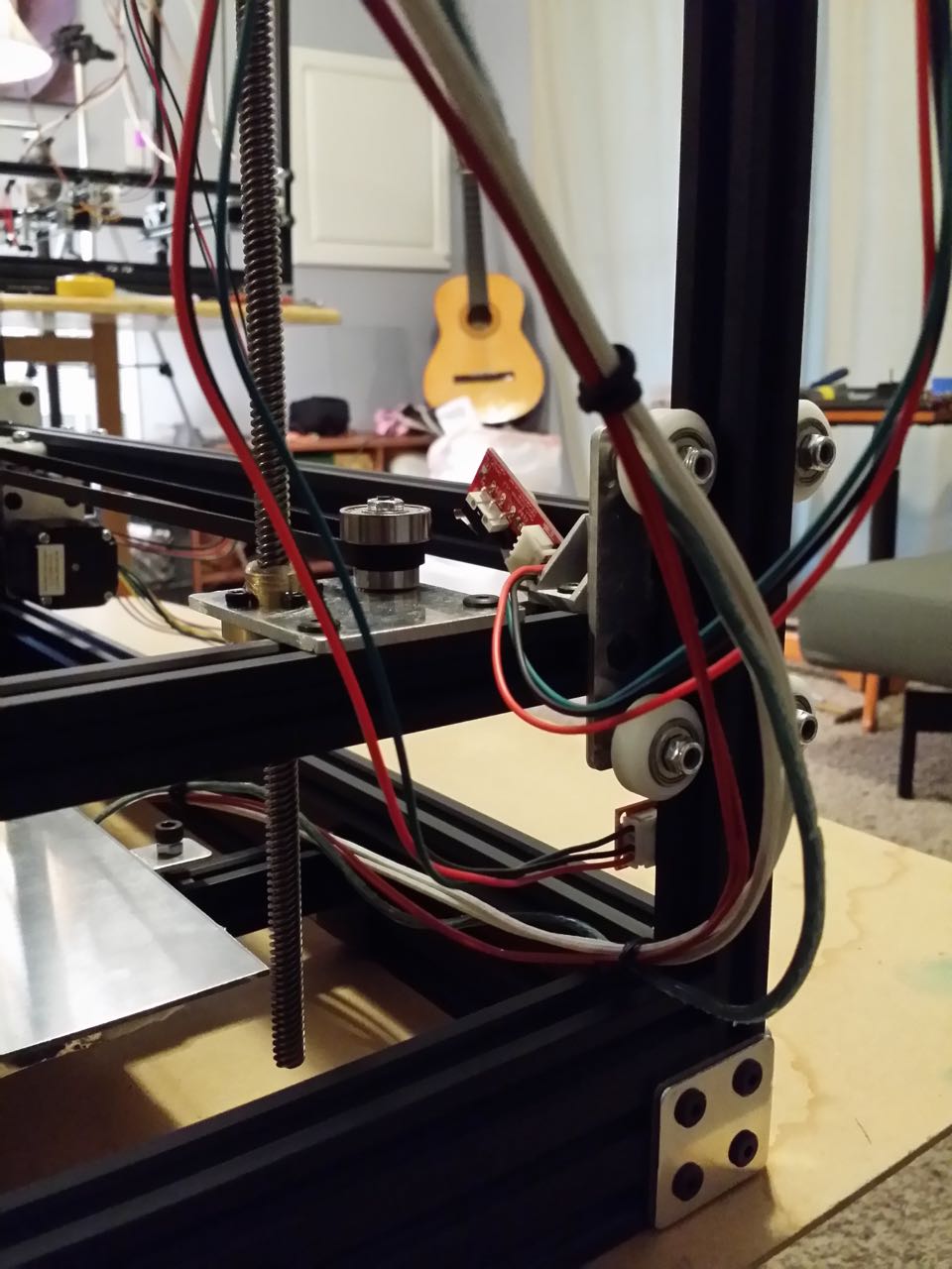
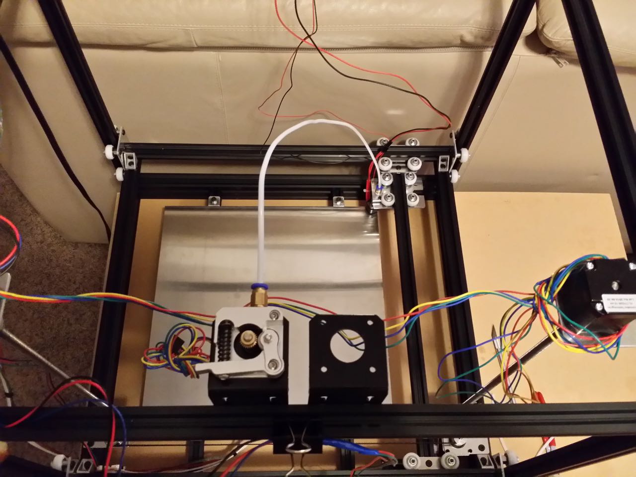
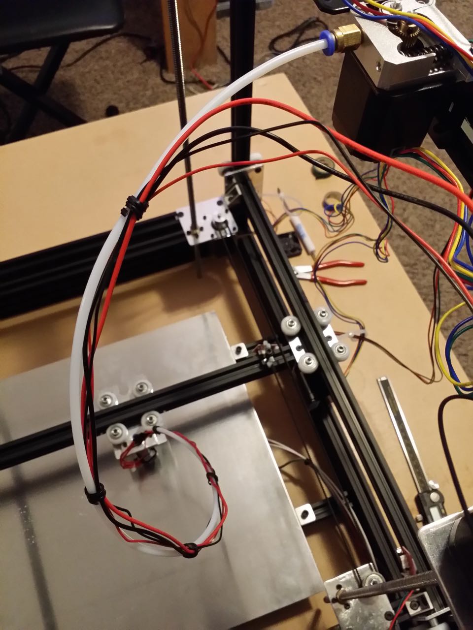
· The
printer's 12VDC supply is powered off
-and-
· Any motor spindle being rotated by manual force does not exceed 1 revolution per second
Operating the
motors quickly (especially belt driven ones) generates feedback voltage into
your electronics boards and can damage the stepper boards or ruin the Mega chip
(sometimes just one I/O pin, sometimes times the whole chip). Do not attempt to
manually move any axis while the RAMPS 12VDC bus is powered on -- in addition
to ruining printer parts, you might also possibly put your hands in harm's way.
Plug the serially-combined Z motors' cable into either of the Z motor headers.
If your motor harnesses have a red wire on the outside, plug the red wire
oriented over the Z motor header pin marked 1B. If you don't have a red wire on
the outside, don't worry about it and just pick an orientation.
http://www.neveroddoreven.com/cobblebot/20150824_201757.jpg
Plug your extruder motor cable into the E0 motor header, with the red wire
again going into pin 1B.
http://www.neveroddoreven.com/cobblebot/20150824_201843.jpg
Ensure your Z motor and extruder motor cables are temporarily secured to the
top rails and out of harm's way.
Fasten two medium zip ties and one small one into a hanger as shown in this
photo. It's ugly for now -- at some point you will find a more eye-friendly way
to suspend the cables 50mm away from the outside rails.
http://www.neveroddoreven.com/cobblebot/20150824_202709.jpg
Using a medium zip tie, make a loose loop around the Y motor and endstop cables
as shown in this photo, and insert the free end of the zip tie deep into the
top slot on the Y rail. You are aiming to suspend the Y motor cable 50mm away
from the wheels so it doesn't get caught in them during operation, and might
need to trim the zip tie a bit to get the length right. Run the Y motor and
endstop cables up and fasten them to the end of the wire hanger you made just
earlier. Connect the Y motor cable to the Y motor header with the red wire
going into pin 2B.
http://www.neveroddoreven.com/cobblebot/20150824_211653.jpg
Make another medium zip-tie loop around the X motor cable and slide it into the
end of the rail that the X motor is mounted to. Run the cable up through the
same zip-tie wire hanger with the Y cables, and plug it into the X motor header
with the red wire on pin 2B.
http://www.neveroddoreven.com/cobblebot/20150824_211713.jpg
http://www.neveroddoreven.com/cobblebot/20150824_211952.jpg
Between the X stepper driver socket and the large flat yellow capacitors, you
should find a small header that provides the power supply voltage (12VDC). Plug
your small 40mm x 10mm fan into it with the red +12V wire on the side closest
to the center of the board. On one of my boards this header was not soldered
on, so I just wired my fan directly together with one of the green screw-down
12VDC inputs (it's electrically identical).
http://www.neveroddoreven.com/cobblebot/20150824_212300.jpg
Examine your printer cables hanging here and there, and find ways to tie the
cables to each other and/or pin them against various rails to keep them outside
of the printer gantry. You want the printer to operate in all axes freely, without
a wire getting pinched by a wheel or yanked out during axis movement. Remember
to manually move things slowly to protect your electronics.
TODO: document better cable securing in required places
You have finished the basic required wiring. Do not plug your CB power supply
into the RAMPS board yet!
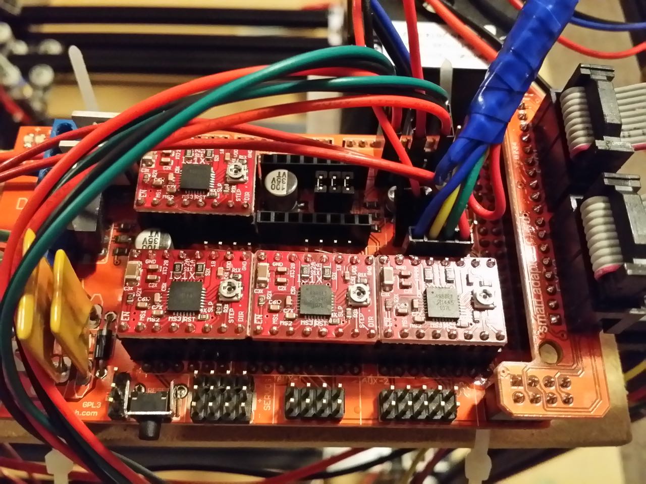
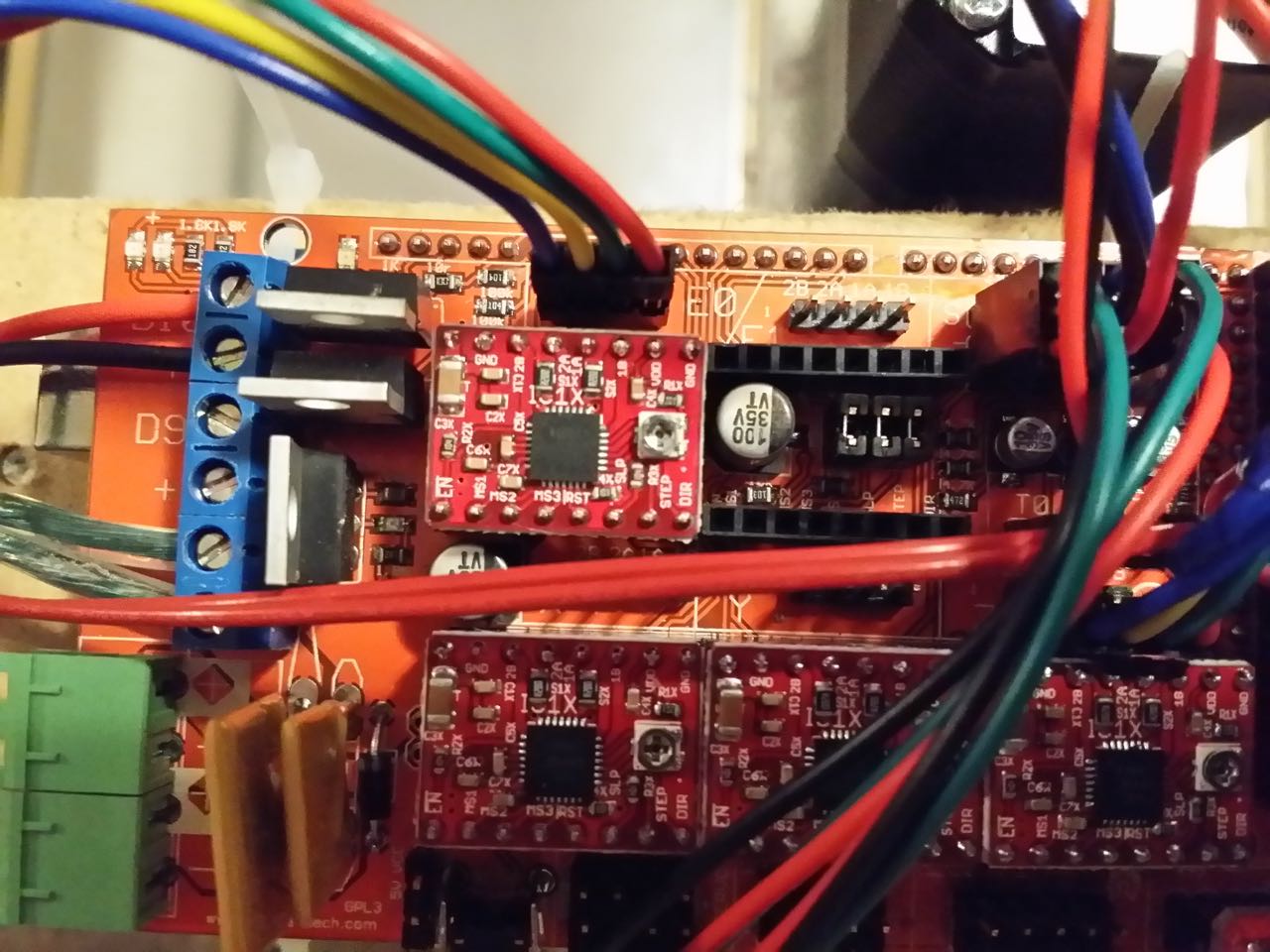
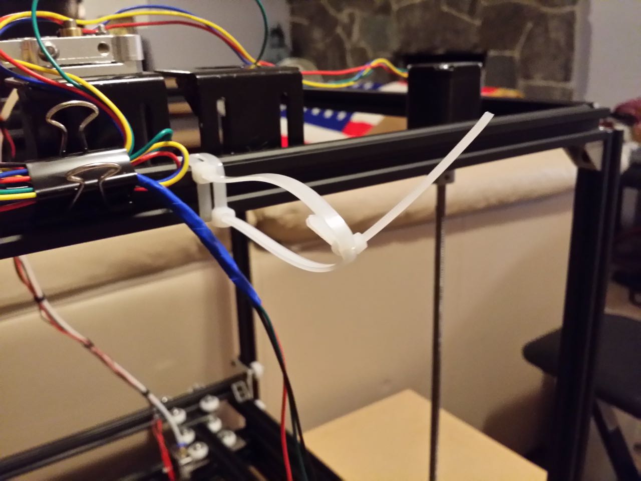
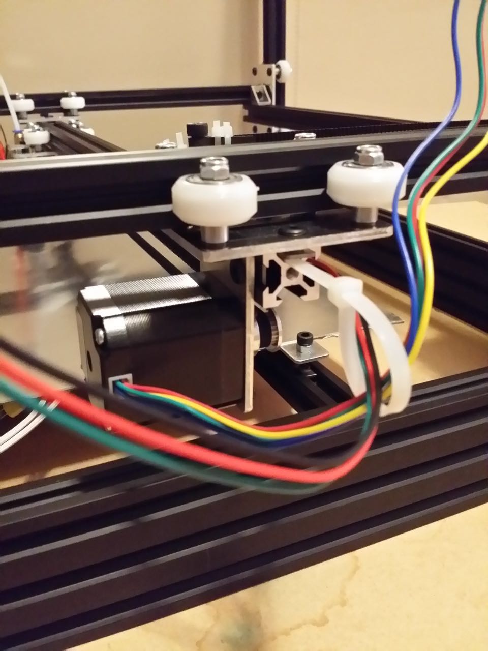
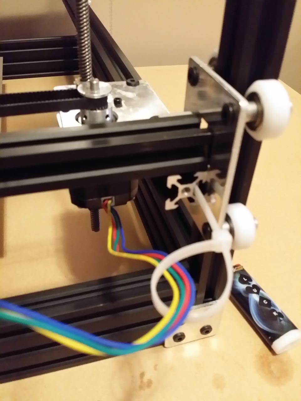
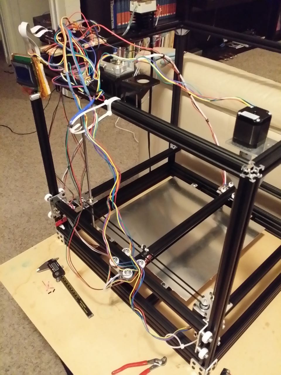
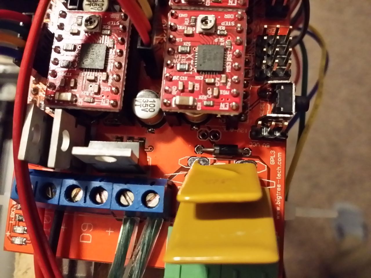
Re: Building a working Cobblebot gantry
Posted: Sat Aug 15, 2015 2:20 pm
by neveroddoreven
Part 7: Firmware and wiring/component checks
You will need:
· A PC USB A to USB B type cable (common printer or USB disk cable)
· A voltmeter capable of measuring 200 to 600 millivolts DC, and also measuring 11 to 13 volts DC
· A flat head trimpot screwdriver, or a very small plastic or ceramic screwdriver, or a metal jeweler's screwdriver will work with some risk and a very steady hand, or perhaps even a well-trimmed paper cotton swab stick might become a non-conductive screwdriver with effort
· A small flathead or cross head screwdriver for adjusting the trimpot on the CB power supply
· A computer running Windows, Mac or Linux
· An external USB hub that is powered by its own power supply, that you are willing to let be destroyed in order to save your computer if something goes wrong
· A little bit of The Internet
· A spool of PLA filament at the correct diameter for your hotend (1.75mm or 3.0mm)
We are going to flash the latest development Repetier firmware (v0.92.4 at the
time of this writing). It is stable and easy for novices to configure, thanks
to Repetier's configuration web tool. You are more than welcome to instead
configure and flash Marlin firmware or something else, if you already know how
or can get the instructions elsewhere to tune and reconfigure the printer
sources. Repetier works with just about every free and paid slicer available,
and has added serial line efficiency/integrity when you use the free
Repetier-Host printer interface software.
To get started, download this initial A4988-optimized configuration file for
Cobblebot Basic with Hexagon to your computer (updated as of 28-Aug-2015):
http://www.neveroddoreven.com/cobblebot/Configuration.h
Now upload the Configuration.h file in the "Upload old configuration"
section of this page:
http://www.repetier.com/firmware/v092/
You will be presented with a lot of options. If you want to make it easier, you
can change the first option "Configuration level" to Normal or
Minimum. Nothing will be lost, you just won't have to look at so many things,
and you can always re-enable the Expert view later.
You will need to edit the following settings on these sections of the initial
firmware.
General:
· No changes for now.
· The EEPROM feature is enabled and storing frequently changed settings to slot 1.
· The serial baud rate during printer operation is set to 250000 baud speed (reflashing still runs at a safe slower speed). If you are unable to use your printer with your computer later, try reducing this value to 115200 either by using the LCD menu configuration, or by setting the firmware configuration to 115200 and then switching the EEPROM setting to the other slot (or to EEPROM disabled).
· The printer dimensions are undersized at 300mm^3 for now to protect your printer mechanics during calibration.
Mechanics:
· If you are using A4988 or DRV8825 at 1/16 steps, no changes for now. If you are using DRV8825 at 1/32 steps (recommended), double the Resolution setting from 80 to 160 for both the X axis stepper motor and Y axis stepper motor.
Temperature:
· If you are using A4988 or DRV8825 at 1/16 steps (recommended), no changes for now. If you are using DRV825 at 1/32 steps (overkill), double the extruder step per mm from 95.5 to 191.
· If you have a second extruder, or you have extra gizmos like part cooling fans and extruder fans, maybe now is not the time to introduce them, for simplicity's sake. Let's stick to getting your printer going first, and then it'll be easy to add the extras on after you prove the mechanics and boards are working.
· If you do not have a heated bed yet, disable the checkbox "Enable heated bed support".
· If you have a Keenovo heated bed, verify on the little business card it came with says "NTC" (meaning a glass thermistor) and "006" (the Marlin value for the typical Epcos 100k thermistor commonly in use). If these are present, then go with the first Epcos value already preset in the heated bed section's "Temperature sensor" value. If it came with a different thermistor, proceed to the next bullet below.
· If you have some other heated bed, you will need to determine what kind of thermistor you have, and select it in the heated bed section's "Temperature sensor" value. It is critical to get this right or your bed temperature might be dangerously off.
· For the heated bed temperature manager, we are going with "Bang bang - switches simple on/off". This is a relay-friendly setting and usually quite sufficient for heated beds, and does not tax the Mega chip with extra calculation overhead.
· If you are using the CB stock Hexagon hotend, it should have come with something equivalent to a typical Epcos 100k thermistor. We will use the first Epcos value already preset in the heated bed section's "Temperature sensor" value. If your Hexagon is using a different thermistor, proceed to the next bullet below.
· If you have installed some other kind of hotend besides the Hexagon supplied by CB, you will need to determine what kind of thermistor you have, and select it in the Extruder 0 section's "Temperature sensor" value. It is critical to get this right or your hotend temperature might be dangerously off.
· For the Extruder 0 temperature manager, we are going with "Dead time control - easy to understand, stable". This does not require extra calibration steps that are required for using PID control, it yields comparable temperature control to PID, and doesn't experience small over-temperature spikes when first warming up like PID control does.
Features:
· No changes for now.
· Don't mess with the "Enable sd support" checkbox, since the CB LCD configuration already sets it up for you.
User Interface:
· Change the language to your preference.
· Change the Printer name and Printer company to whatever you like, keep it under 16 chars each if you want to read it all.
· If you did not add the CB-provided LCD display controller, change the Display Controller option to "No Display".
Manual Additions:
· Nothing for now.
When you get to the Download section, the first time you go through this you
will want to download the complete firmware including the settings. You will
receive a zip file, which you will need to unpack to a folder and put somewhere
on your computer for frequent use and safe keeping. After this initial
download, you don't need to download the complete firmware again unless there
is a new firmware version out that you need because something isn't working
well enough for you.
In the future, if you are only making configuration changes, you only need to
download the Configuration.h file, and replace the old Configuration.h file in
the unzipped firmware folder from earlier with the new one. It is not
recommended to hand-adjust the values in the Configuration.h file because all
the settings are duplicated in a JSON-formatted comment section at the bottom,
and if you don't also update those JSON comments, your changes will be lost
next time you re-upload your Configuration.h file for editing in the web form.
Now that you have the complete firmware with your initial Configuration.h file,
you are ready to flash it to your Mega board. Here are PC instructions, if you
are on Mac or Linux you'll have to fumble through something similar.
Download and install the latest Arduino Software IDE (1.6.5 at the time of this
writing):
http://arduino.cc/
While you are at it, also download (for free) the Repetier-Host software. You
do not need to accept the Repetier-Server software unless it's something you
want. You will need to use Repetier-Host to adjust your firmware's EEPROM
settings, and then you can use something else to control your printer if you
like (I use Simplify3D paid software). When you go to eventually use the
Repetier-Host software (or any other PC slicer/controller software) with your
printer, you
http://www.repetier.com/
Open the Arduino application after installing it. Go to File > Open, then in
the file dialog, browse to the firmware folder that you unzipped earlier, go
into the Repetier-Firmware subfolder, then the Repetier subfolder, and open the
Repetier.ino file. You will see another Arduino window open with the title
"Repetier" -- now you can close the other Arduino window that you
originally started.
In the Arduino application, do the following:
· Go to the Tools menu > Boards, and select "Arduino Mega or Mega 2560". If you don't see that option, then instead select "Boards manager" at the top of the menu list, then in the UI that appears select "Arduino AVR Boards" and either install or update it, then you should find the menu option available.
· Go to Tools menu > Processor and select "ATmega 2560 (Mega 2560)".
· Go to Tools menu > Programmer and select "AVRISP mkII".
These settings should be remembered by the app in the future until
you change them.
Let's inventory your current list of serial ports. In the Arduino app, go to
Tools menu > Ports and take down the list of current serial ports. You might
have none.
This is your last chance to safely check over everything and ensure nothing is cross-wired, and no pins or connectors are shorted against a rail or other part. You also should double-check that your stepper drivers are inserted in the proper orientation -- find the little silver wheel with a cross in it, on an A4988 (square chip) it should be on the side closest to the AUX-4 header where the LCD is plugged in, and on the DRV8825 it should be on the side closest to the green 12VDC power connectors.
These instructions assume you have done nothing special to your Mega or RAMPS
board, and allowed them to be configured such that the Mega board receives its
5V logic power from the USB bus without requiring the CB power supply to be
energized. You are free to change this in the future if you have too many 5V DC
devices, but for now let's keep it simple and let the Mega chip run on USB
power.
Ensure that your RAMPS board is not plugged into any power supply, and that you
did not connect the Mega board to any power supply either. Unplug the
sacrificial external USB hub from your computer, and unplug everything else
from the hub. Connect the USB cable to the Mega board, and then connect it to
your external USB hub. If you don't see smoke, and the Mega lights come on,
then plug the USB hub into your computer. If you are using Windows, you may be
prompted to download device setup drivers -- let it do stuff automatically and
it should work out fine (installs a serial port driver).
In the Arduino app, re-examine your list of serial ports and find the new one.
That's your printer. FYI, in Windows, it might change names later if you move
the USB cable around to a different port (no big deal). Select the
freshly-added serial port.
In the Arduino app, click on the checkmark button (Verify). The app should
compute for awhile, and then report "Done compiling" in the lower
status bar. Now click the right arrowed icon button (Upload). After around one
minute, it should return with "Done uploading". If it does not,
consult with the community for solutions. Once uploaded, you can close the
Arduino application until the next time you will reflash your printer.
If you are using the LCD controller, you should see it come to life and display
some Celsius room temperatures for the hotend (and heated bed if you have it).
The rotary wheel menus should also work, but do not play with the menus! Do not
move anything or change anything! At least, not yet. If you do not see the LCD
come to life, double check that your LCD ribbon cables are firmly seated in the
right order (the EXP2 LCD ribbon should plug into the L-shaped "smart
adapter" header that is closest to the Z stepper driver).
http://www.neveroddoreven.com/cobblebot/20150826_184535.jpg
Check that your temperatures seem correct at room temperature. You will need an
accurate way to measure ambient room temperature. This might be a good wall
thermostat that is nearby, or it could be an inexpensive digital cooking or
room thermometer.
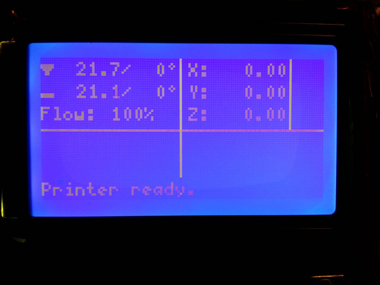
1. If your thermometer is portable, leave it sitting on the center of the build platform (turned off if digital) and unplug any USB or power cables from the printer.
2. Ensure that nobody has been touching the printer within the past 30 minutes, and that there is no air blowing on the printer, and that the room temperature is stable (morning time is best before any heaters or A/C turn on).
3. Plug in the printer cable.
4. Check that the LCD temperatures on the thermometer and the hotend are within two degrees Celsius. The LCD nozzle icon is funnel shaped, on the top left line. If you did not connect an LCD, you will need to use the Repetier-Host computer software to check these values for now.
5. If you have a heated bed, check that the heated bed and hotend temperature are close to each other within two degrees Celsius. The bed is the flat icon, second down on the left.
6. If the temperatures look alright, you're all set, move on past this list to the next step.
7. If any of these temperatures are not close to each other within about two degrees Celsius, then you have an incorrect thermistor setting in the firmware, or you have a defective thermistor.
8. If you don't actually have a heated bed and it shows a "def / 0° " bed temperature, you need to go back to the instructions for downloading your configuration file, turn off the heated bed option, then update your local Configuration.h and re-upload the firmware to your printer.
9. If the printer shows "def / 0° " for the nozzle or the bed, reset the printer using the reset button on the LCD or on the Mega board, and there will be a momentary temperature on the LCD right before it changes to show "def". If it shows somewhere around -50.0° your thermistor circuit is probably open, and if it shows somewhere around 500.0° your thermistor wires are probably shorted together either at the hotend or in the header connector. Check your wires and connectors, and if you can't solve it, try swapping the hotend and bed thermistors to see if the problem moves. Either your thermistor is defective, or that Arduino input pin is defective (there are sw/hw workarounds to remap to another pin -- check with the community for help).
10. NOTE1: if you have an infrared laser thermometer, these work poorly on reflective metal surfaces, so you will need to prepare black-taped-over surfaces in advance if you want to use it for calibration.
11. NOTE2: I do not have a good recommendation to test hot nozzles or beds at operating temperature, except for an infrared thermometer. You will need to experiment later with melting PLA or ABS at the expected temperature and see how it turns out.
We are going to pre-adjust your stepper motor Vref trim potentiometers
(trimpots) to prevent an initial overvoltage. Find a way (tape, alligator clip
or similar) to attach or prop up your voltmeter's negative probe against the
metallic shield on the Mega USB connector.
http://www.neveroddoreven.com/cobblebot/20150826_194813.jpg
If you are fortunate ![]() enough
to be using the A4988 drivers:
enough
to be using the A4988 drivers:
You will now have the luxury of adjusting your Vref casually without having to
actually power up the stepper drivers and motors. Place positive probe against
the USB metal shield and confirm your voltmeter drops to 0.0 VDC. You will need
a steady hand for this next step. Go to each stepper driver's trimpot and place
the probe tip directly on the metal trimpot, without rotating it. Take special
care not to slip and put the positive probe elsewhere on the board, or you
might short some stuff together and damage the stepper driver board. Check the
voltage, then use a very small screwdriver (ideally nonmetallic) to adjust the
trimpot in either direction slightly. Measure the voltage again, and re-adjust
in the correct direction until it is at the recommended initial Vref voltages
below.
If you are fortunate ![]() enough
to be using the DRV8825 drivers:
enough
to be using the DRV8825 drivers:
You cannot measure the stepper Vref voltages until we energize the stepper
driver boards and motors a little later with the CB power supply's 12VDC bus.
Instead, for now you're going to set them in a guessed position that is safe
enough and somewhat close to the actual voltage you will eventually set. Get a
magnifying glass if you can't see the trimpot clearly, and then have a look at
this thread for close-up photos and a suggested initial trimpot position.
Later, when you power up the RAMPS board, refer to the A4988 section above for
the procedure to check and adjust the actual voltage, and refer to the DRV8825
suggested voltages below.
viewtopic.php?f=4&t=1303&p=8537&hilit=vref#p8537
Initial recommended voltages (these are on the low and safe side, configured
for a series-wired pair of Z motors and a direct drive Bowden extruder):
A4988: X and Y at 0.65 V, Z at 0.72 V, and E0 at 0.72 V.
DRV8825: X and Y at 0.45 V, Z at 0.52 V, and E0 at 0.55 V.
After adjusting the stepper driver trimpots, make some sort of temporary
support structure for your 40 or 50mm fan, which you can use to position the
fan over the top of the RAMPS board and blowing down on the drivers. I used zip
ties to make stiff movable mosquito-like legs that I can position in the
various board mounting holes. Other users report better efficiency blowing air
beneath the DRV8825 drivers, but I personally have never had any overheating
issues on a heavier printer with top-down DRV8825 air cooling and little
mini-heatsinks attached to the tops of the stepper driver chips.
http://www.neveroddoreven.com/cobblebot/20150826_205045.jpg
Move the gantry slowly so that the hotend nozzle is at the X/Y center of the
build plate, and the Z axis has been raised to 80 to 100 mm high on the Z axis.
Ensure that both sides of the Z axis are visually somewhat level with respect
to the build plate, to prevent binding.
If you have a fire extinguisher, have it handy just in case, for the rest of
these instructions, and also for at least the first 20 hours of printing on
your brand new printer. A large carton of baking soda or a bucket of sand might
work if you have nothing else. Do not use water on an electrical fire.
Plug your CB power supply into the wall, but do not plug it into the RAMPS
board yet. Do not plug in a wall-powered heated bed at this time (if you have
one). Switch the power supply on, and check that the power pins are getting
about 12.0 to 12.5 V DC in the correct polarity with respect to how the RAMPS
board is labeled for + and - voltage. Now switch off and unplug the CB power
supply, and wait for the little green LED in the power supply to go out. Plug
the CB power supply's cable with the green quick disconnect headers into the
RAMPS board, and then plug in the CB power supply and switch on the wall
voltage. Verify that your 12V DC fan starts to spin, and no magic smoke escapes
anywhere. You will not hear the stepper motors engage because they are disabled
in software on power up by default.
Click the LCD rotary knob to open the Repetier LCD menu. DO NOT SELECT ANY HOME
COMMANDS AT THIS TIME -- IF YOU DO, IMMEDIATELY HIT THE RESET BUTTON ON THE
RAMPS BOARD!
DO NOT ENABLE THE NOZZLE OR BED HEATERS. We will work with those later, and
heating them up now might burn you during the next steps.
If you did not connect an LCD, you will need to use the Repetier Host computer
software to complete the following steps, and you'll have to configure the
printer dimensions in that software to 350x350x350mm for now.
For the next set of instructions, if there is any unexpected motion, such as
wheels crashing into rails, or belts jumping on their toothed pulleys, or
cracking or heavy grinding sounds, you need to be prepared! Know where the
reset buttons are on the LCD board and the RAMPS board. Either will function to
immediately halt all printer activity. Alternately, killing the CB power supply
will halt motors without halting the Mega chip. Also, in the future, when you
adjust nonvolatile Repetier or Marlin EEPROM memory settings (more on that
later), it sometimes causes the printer to autonomously start moving, so be
ready to reset it then too (or better yet, only change EEPROM settings with the
CB power supply turned off).
In the LCD menu, go to Position > X Position. You will see it list the
position at 0.00mm because it hasn't been homed since startup. Rotate the dial
clockwise slowly until the LCD says you have moved 50mm. Verify the printer X
axis has moved so the Y carriage has traveled further away from the X-min
endstop switch. Don't worry about checking the 50mm distance for now. If your X
motor doesn't have quite enough power to drive the axis due to minor binding
during parts of the wheel rotation, it will try to move and make little
grinding jerking motions. That's okay for now, just verify the direction it's
trying to go.
Repeat the same steps above for the Y axis, verifying the Y carriage travels
further away from the Y endstop switch.
Repeat the same steps again for the Z axis, but always keep a close eye that
your nozzle head does not crash into your build plate. This time you only need
to go about 10mm, not 50mm, and ensure the Z axis attempts to climb up the
rails. If it does not climb, we will work on that, but at least it should not
be descending. It definitely should not be twisting in opposite Z-screw
directions on each side -- if that happens, your serial wiring is wrong and you
need to re-do it (or you are parallel wired and one of them is plugged in
reverse of the other).
If any of your X, Y, Z axes are going toward the direction of their respective
endstop switches, then power down the CB power supply and wait for its green
LED to go out. For that motor, unplug its connector from the RAMPS board, flip
it to the other direction, and plug it back in. Try moving it in the LCD menu
again, and confirm it is traveling as expected, without running your wheels
into the rails.
After verifying your axes go away from their Min endstops with climbing
position, you can slowly adjust the Vref voltages up on each one to overcome
any minor binding. If you reach more than 0.85 V on an A4988, or more than 0.62
V on a DRV8825, or the motors have excessive grinding/humming noises when
sitting still at any rotational position (Z axes sometimes hum like running
water pipes normally depending on current angular position), or the motors get
hot enough over time that you can't keep a hand on them for more than three
seconds, then your voltage is too high and something needs to be done about the
excessive binding on the axis. Consult with the CB community for help.
Make a visual estimate of the distance moved on each axis. Move the rotary
wheel slowly. If you move it 10mm and it goes 20mm, or vice versa, then that
axis resolution (steps per mm) need to be adjusted, often times halved or
doubled based on mismatches in your firmware vs your actual stepper driver
jumper settings. Although you initially set these X/Y/Z resolution values in
the Repetier Firmware web config page, they are now ignored and instead stored
and loaded from the Mega EEPROM, even after a power reset. You can overwrite
and backup these EEPROM settings with the Repetier-Host computer software (Menu
> Config > Firmware EEPROM Configuration) without having to reflash the
whole printer firmware using the Arduino Software app. There are also a lot of
EEPROM settings that can be edited in the Repetier LCD menu and stored there to
EEPROM, but the X/Y/Z resolution is not one of them. If you find the EEPROM
feature to be irritating, you can turn EEPROM usage off in the Repetier
firmware web config site under the General section, and reflash your printer
every time, although this slowly wears out your Mega flash storage.
Once your axes are moving mostly okay, and in the right directions, we will
verify the endstops are working. Keep a very close eye on your wheels and make
sure they never run into the 90 degree corner brackets, or a sharp line will be
cut into the wheels that might affect print quality for awhile depending on how
deep the cut is. The wheels should not push past the switch lever/button and
bind or shove the switch board. Also be very careful that the Y carriage plate
never drives into the Z axis lead screws, or into the side of a motor. All of
these things can damage your printer, either now in a gentle fashion, or more
violently later when the printer is autonomously going at full speed.
Slowly use the rotary control in the LCD Position menu to move the X axis
closer to its endstop, until it is triggered and the axis stops moving even
when you keep slowly turning the LCD rotary control. If you don't hear the
X-min endstop click, or it clicks but the switch light doesn't come on, or the
wheels are getting to within 1mm of hitting a rail or corner bracket, or the
wheels/brackets are actually pushing on the endstop board itself, then you've
gone too far -- stop and back up. Double check that the switch is actually
being audibly engaged by the wheel or bracket. If that's not the problem, then
you have an issue where the switch is not sending the signal, or the RAMPS
board is not detecting it (did you switch to a different kind of endstop
hardware?), or the switch is not connected properly. Consult the community for
help.
After confirming your X endstop works and ceases further negative direction
moves, use the controls to move the X axis back to the center of the printer.
Repeat the same steps above with the Y axis. Do not do anything with the Z axis
for now.
Use the controls to move the Y axis back to its home position against the Y-min
endstop. Verify that at the Y-min position, the nozzle is over the build plate
and within 5mm of its edge closest to the Y-min endstop. If it is not, now is
the time to make the final adjustment of the Y-min endstop position. Tighten
the endstop down firmly if it is loose.
Use the controls to move the X axis back to about 10mm from the X-min endstop.
Very slowly approach the X-min endstop switch, and keep a really close watch
that the Y carriage edge does not crash into the Z-screw on the X-idler side.
When the X-min endstop is engaged, the Y carriage should be 2mm from touching
the Z-screw. If it is not, now is the time to make the final adjustment of the
X-min endstop. Tighten the endstop down firmly if it is loose.
The Z axis must be finely leveled before it can be adjusted. Before doing this,
you should prepare your build surface as you would use it during printing
(minus treatments such as hairspray, glue etc). Install your glass plate, Fleks
plate, painters tape, whatever, and fix it down to the aluminum plate with #2
bulldog clips or whatever hardware you're using. Ensure that the clips do not
overlap into the build area in a way that they could catch on the nozzle head
as it passes by.
Verify that your build plate is level with the printer's base rails. Use a
straightedge across the base 20x60 rails and a depth gauge or fine ruler to get
your build surface as level as you can respective to the base rails. Tip the
printer up on side, or hang one side over the edge of your work surface with a
friend holding it steady, and loosen/tighten the build plate rail corner
brackets as needed to adjust it into level position in all dimensions. This can
take awhile but is worth the effort to ensure your part walls are dimensionally
square in the Z axis.
Power off the CB power supply and wait for its green LED to go out. Gently move
the X axis so it is at X-min home position, and then move the Y axis to its
middle position. Lower both Z screws by hand until the nozzle gently just
touches the build plate and the gantry is level by visual estimate as compared
to the build plate. Per your previous X-min switch adustments, the nozzle
should now be about 5mm or so from the edge of the build plate on the X idler
side.
Raise only the Z-screw that is farthest away from the hotend by about 5mm --
the Z axis is now intentionally not level. Turn on the CB power supply and use
the controls to move the X axis a little bit, say 5 or 10mm. Make sure it is
not scraping on the build plate, and then move it to its current maximum
position of 350mm. It will refuse to go any farther by software limitation. Now
hit the LCD or RAMPS reset button, let it reboot and forget where it was, and
you can get it to keep moving further on the X axis a bit more until the nozzle
has reached to within 5mm of the X motor side of the build plate. The purpose
of using the X axis motor is to move the X rail without disturbing the Z screw
on the X idler side.
Turn off the CB power supply and wait for its green LED to go out. Manually
lower ONLY the Z screw on the X motor side until the hotend nozzle just touches
the build plate. Try to manually move the X axis back to the opposite side of
the build plate. If it won't go or begins to scrape the build plate, raise the
opposite side's Z screw a bit until the nozzle just barely clears the plate by
0.5mm to the other side. Lower that side's Z screw until the nozzle just
touches the plate. Your Z axis should now be reasonably level but might need
fine adjustment.
Turn the CB power supply back on and use the controls to raise the Z axis by
2.00 mm. Slowly control the X axis from one side of the build plate to the
other and keep a sharp eye on the hotend nozzle to ensure it consistently stays
at 2.00 mm away from the build plate all the way across. If it starts to get
closer or farther, then you need to stop, temporarily turn off the CB power
supply, minutely adjust the offending Z screw just enough to get the nozzle
back to 2.0mm distance from the build plate, and then power up the CB supply
again. Keep doing this back and forth until the nozzle stays a consistent
distance over the entire X axis when the Y (and therefore the nozzle) is
sweeping back and forth along the middle of the plate. Once you have both sides
even, use the controls to move the nozzle to the dead center of the printer,
lower it until it can just barely hold down a piece of paper until you can pull
it out with mild force. Move the Z-Min endstop up until it touches the bracket
and switches on, and screw the switch down moderately tight but allow just
enough so you can move the switch slightly with moderate manual force (for fine
adjustments later). Your Z min axis is set for now, until you add another layer
on top of your build plate. Do not adjust your Z screws any further, and never
ever EVER turn them by hand again or you'll throw it out of level.
Moving the Y axis back and forth across the plate might not show the same
evenness at the nozzle tip. Either your build plate is out of alignment on the
Y axis, or your gantry exhibits a little Z sag on the side opposite the Z
screws. The easiest thing is to realign your plate to be flush against the
nozzle at all four build platform corners, without adjusting your Z axis. If
you do this, double check your build platform is reasonably flat compared to
the build frame around it. If it is not, you will be able to print but your Z
axis might not be perfectly square. This is okay if you want to just get
started printing stuff and proving the equipment works.
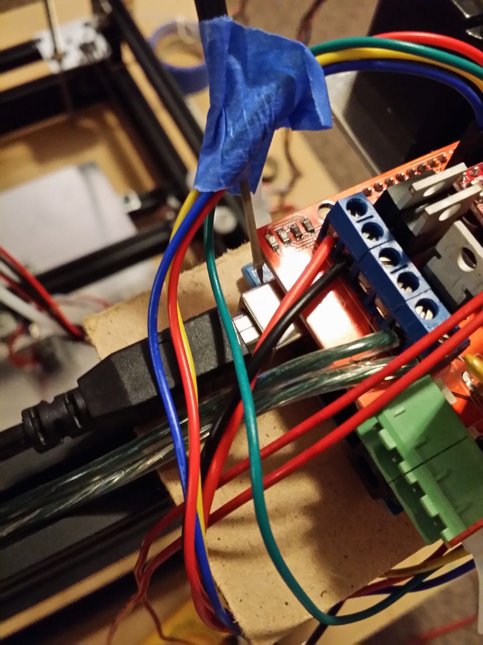
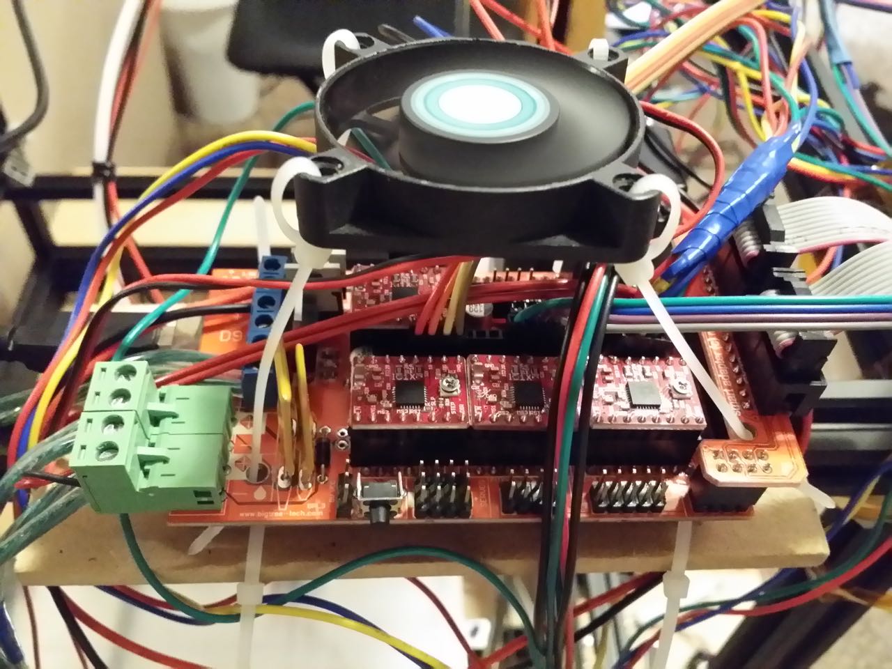
· If you really want to be precise, you'll have to try returning to the same techniques you used in earlier gantry building instructions to level the gantry with identical length sticks and adjusting/raising/retightening the Z plate brackets on the non-screw side. Modify the process to also use the sticks measuring at either end of the Y rail when positioned at the left, right and center of the build plate. Be very careful, don't loosen anything you don't need to, and make very slight adjustments or you could introduce unwanted skew and binding into the printer.
· My experience is that if you can't measure more than 0.5 millimeter tilt in Z-flatness in any direction from one side of the printer to the other, it is level enough for the vast majority of home-printed parts. The skew will be hardly noticeable even when breaking out the squares and calipers. Also, this slight amount of sag should stay fairly constant as the gantry travels up the rails as long as your wheels aren't dragging unevenly, so you won't have problems with layer depths and uneven bonding.
· My recommendation: Reduce the gantry's Z sag to less than one millimeter difference between screw vs non-screw sides as measured in distance from the horizontal gantry rails down to the base plate rails, and then adjust the build plate to make up the difference. Adjust your build plate height using its supporting rails and screws until the nozzle is the same distance everywhere at all points over the plate.
After leveling the bed, do one last nozzle height check. Put a piece of paper
between the nozzle and build platform, and reduce the height until the paper is
slightly pinched but can still move around somewhat freely. Adjust your Z
minimum endstop so it just begins to engage. Home the Z axis using the LCD, and
verify the paper is pinched the same way. Move your nozzle to various points on
the build plate around the edges and center, being careful not to drive the
carriage into any gantry parts. Check that the nozzle height at all areas of
the build plate just slightly pinches the paper in the same way everywhere.
Failure to do this step sufficiently will result in uneven first layer height,
which can cause many different kinds of problems printing as well as the part
either not sticking or sticking too much to the plate in different areas.
It's now time to finalize your build area size. Before you do this, use some
calipers or a fine ruler to verify that your X,Y,Z axes' step per mm are
calibrated correctly. Try moving 100mm on any one axis, verify the distance,
and adjust the steps per mm in the firmware as needed. Changing the calibration
values goes faster if you just turn off the CB power supply, use the Repetier
Host software > Menu > Config > Firmware EEPROM Configuration to set
the X,Y,Z-axis steps per mm. Then after changing and saving the values, reset
the controller and turn the CB power supply on, and retest the distances. Consult
the various calibration guides online (or ask the community) to help make
calibration faster with simple math. Get your distances calibrated to within
1.0 mm for now, and you can work on them more after your printer is running.
Use the LCD Position menu to home all axes, inspect the nozzle position on the
build platform, and decide now if you want to increase the non-printing margin
to make room for bigger clips, or to reduce warping/detachment problems due to
heat falloff if your heater doesn't have a lot of evenly distributed power. If
this is the case, move your X and Y minimum endstop switches toward the printer
center to reduce build area according to preference, and use the LCD to re-home
the printer on all axes.
Now move the X axis to the 350.00 mm position. Reset the printer, then go back
to the LCD Position to continue moving the X axis. You will notice the X
position is now reset to 0.00 -- we will use this as a counter. Move the X axis
until it reaches 2mm from striking against either the X motor, or the Z lead
screw next to it, or until an earlier position if you are reducing your build
area as described earlier. Verify your nozzle is still Note the new X axis
position reported on the LCD, and add it to 350.00. This is your X dimension --
write it down.
Home the Y axis, and use the same technique to go from 0.00 to 350.00, reset
the printer, and keep going just until 1mm before the lock nuts on top of your
Y carriage wheels would strike the X gantry plate wheels (or earlier if
reducing your build volume). Add the extra Y distance to 350.00, and write that
value down as your new Y dimension.
Home the Z axis, and then raise the Z axis until the gantry wheels are about at
350.00mm height. Reset the printer as before, and keep going until the Z axis
is 5mm away from the corner brackets attached to the frame's top rails. As you
are raising the gantry, keep a close eye on all the cables that none get
pinched in a wheel, or pinched between the gantry rails. Anything that looks
suspicious should be taken care of so you don't have cable problems during
printing. Now slowly keep raising the Z gantry while carefully checking each
top wheel in the gantry, until any of the wheels are 1mm from striking the top
corner brackets. Add the distance to 350.00 and write it down, this is your new
Z dimension.
Connect to the printer in Repetier-Host computer software, and use the Firmware
EEPROM configuration menu item to update the X,Y,Z max length values. Turn off
the CB power supply, save the values to EEPROM, reset the controller, and turn
the CB power supply back on.
Open your Configuration.h file in the Repetier Firmware web config tool, go to
the General section, and update its X,Y,Z lengths to the new dimensions you
just collected. Also make sure your X,Y,Z steps per mm distances are updated in
the Mechanics page. Save your new Configuration.h file. It's up to you if you
want to reflash the Mega board just in case you erase the EEPROM settings
later.
We will now test your nozzle heater, without actually feeding any filament into
it. Have your fire extinguisher ready. Use the LCD Extruder menu to set the
nozzle "Temp. 1" to 170°C (the minimum config), and then use the Back
menu items to go back to the main screen on the LCD. Verify the nozzle begins
to heat up, stops at around 170 degrees, and stabilizes at that temperature.
Let it sit stable at that temperature for two minutes, while you monitor
everything closely. It should bounce around between 169 and 171 degrees. A
slight smell, like a mix of new electronics and new kitchen cooking appliance,
is normal. Smoke is not normal for a virgin hotend with no plastic.
Remove the Bowden tube from the extruder motor, and carefully hang it to the
side without removing it from the hotend or letting it touch the hotend. Get a
piece of electrical tape or some device to tape/clamp your plastic filament
reel. Keep the plastic filament tight against the reel while you remove and cut
off around 200mm of filament, then tape the filament reel so the filament
doesn't unwind and cause a tangled mess.
Press on the extruder clamp, feed the loose piece of filament through the
extruder and let about 2mm stick out of the brass fitting on the extruder. You
might find the filament is hard to feed through the extruder's brass fitting if
the filament tip is smashed or snaggled, or if the filament has a strong curl
that makes it catch on the sides of the tube. Try bending the filament so the
first 10mm are really straight. It also helps to trim the tip, or cut it at an
angle, to help it feed through. These same issues will also happen later in the
hotend if the filament end is not trimmed properly.
Now back the filament up so it is exactly flush with the brass fitting where
the Bowden tube normally goes in. Use the LCD Position menu to move the
extruder and push through 100mm of filament, about 10mm at a time because
you'll temporarily lose control if you spin the dial too fast. If there is
binding and skipping, you will need to slightly adjust up your extruder Vref as
described in earlier steps, but you won't likely have these issues until you
apply filament pressure into the hotend. The controller will not let you feed
filament if the hotend is below 150 degrees.
Use a caliper tool or a fine ruler to verify the extruder fed exactly 100mm through,
to an accuracy rate of 0.5mm. You will work to refine this more later. If it is
not accurate, use the same techniques earlier described to adjust the EEPROM
Extr. 1 steps per mm value until the extruder feeds 100mm accurately. Use the
Repetier Firmware web config tool to update your Configuration.h file as you
did earlier with this new number in the Temperature section. It's up to you if
you want to reflash the Mega board just in case you erase the EEPROM setting
later.
If you have a mains-powered silicone heated bed:
Don't plug it into the wall yet. Use a voltmeter to confirm there is 0 volts AC
present at the bed heater's wall plug when measuring between the live prong and
the neutral prong, and also the live prong and the ground prong. Use an ohmmeter
to verify the circuit is open when measuring between the live prong and the
neutral prong, and the live prong and the ground prong. Now use the printer LCD
Extruder menu to turn the heated bed to 100°C, and verify the resistance
between the live prong and neutral prong measures measures somewhere in the
thousands of ohms range depending on its wattage (my Keenovo measure 1616
ohms). Let the controller sit there for about one minute -- a safety measure
should kick in and disable the printer functions. The bed temperature should
change from room temperature to "dec" (meaning decoupled, it thinks
the heater is going like crazy and the thermistor fell off and doesn't pick up
the rising temperature). This is a false alarm because your bed is not plugged
in. Reset the controller, and plug your bed heater's cable into a power strip
with an easily accessible switch (it can be shared with your CB power supply).
Use the LCD Extruder menu to heat your bed up to 50°C, and let it stabilize for
two minutes. It should fluctuate on and off in a slow pattern to maintain
temperature within a few degrees (this is the nature of relay friendly
bang-bang control). Your bed heater is tested.
If you have some other kind of heated bed:
Best of luck! You can probably take from just the last two sentences in the
mains-powered bed testing steps above.
Hang your filament spool up from a thin hard rod, or if you have a spool holder
already, use that. You want the filament to pull easily from the spool, but the
spool shouldn't spin really easily because it could eventually unreel and
tangle the filament. Use the LCD menu to home all axes, heat the extruder up to
195°C (or to your filament's preferred temperature if you know it), and then
raise the Z axis up by 10 mm. Remove the piece of filament from the extruder.
Manually feed fresh filament from your filament spool into the extruder. Slide
the Bowden tube over the filament sticking out of the extruder, and then firmly
seat it into the brass fitting. Squeeze the extruder lever and manually feed
the filament down the Bowden tube and into the hotend. Gently push the filament
into the hotend manually, and verify it does not hang up in the hotend. You
should be able to push with moderate manual force and get the filament to melt
and extrude out of the nozzle.
Congratulations, you have verified all parts of your system except for the LCD
controller's SD card (I'll let you do that on your own).
Re: Building a working Cobblebot gantry
Posted: Sat Aug 15, 2015 2:21 pm
by neveroddoreven
Part 8: Wrapup and post-steps
I suppose we'll find some more stuff to go here. I won't cover actually
printing the first test piece, there are so many great guides out there already
for that.
Post-build tips:
· After your printer has cooled down, turn it back on, start both the hotend and the heated bed to heat up to temperature. As they are heating, use a voltmeter to measure the CB power supply voltage level under its heaviest load. Readjust it to be between 11.9 and 12.1 VDC. Use the LCD menu to disable the heaters, then disable the stepper motors, and check the CB power supply voltage again -- if it is now greater than 12.5 VDC at rest, adjust it down to 12.5 V DC.
· If you have a stepper motor model that features a disconnectable wiring loom at the stepper motor body, it is advisable to use a small piece of stiff sticky tape (perhaps duct tape or similar) to secure the wiring loom so it can't be easily yanked out of the motor body. If this happens while the printer is powered on (by catching a wire on a tool, watch, cuff, etc) there is a strong chance that its stepper motor driver might be electrically damaged.
Re: Building a working Cobblebot gantry
Posted: Mon Aug 24, 2015 10:06 am
by Edogg
If you'd like to
include the link to my power supply repair guide go for it.
http://forums.cobbleverse.com/viewtopic.php?f=4&t=1620&p=11168#p11168
viewtopic.php?f=4&t=1620&p=11168#p11168
Re: Building a working Cobblebot gantry
Posted: Fri Aug 28, 2015 10:01 pm
by neveroddoreven
UPDATE: I've gotten to a complete first draft state. I have modified nearly all sections in the last week, and updated the config file too. Please have a read, and send me notes either as replies or as PMs.
Re: Building a working Cobblebot gantry
Posted: Mon Aug 31, 2015 6:39 am
by Freewill
This was incredibly
informative. My printer is mechanically ready and electronics are operational
as I have used the software to manually move motors. I can't quite figure out
this next part though... I spent the weekend following your instructions and
they cut down alot of the guess work that Cobblebot didn't include in their own
manual.
I went with an alternate build posted in the forms to use CoreXY with the
hexagon hot end placed at the top of the printer frame and the build plate can
be moved up and down using the Z motors.
At this stage I'm setting up the firmware to teach the printer the build space
parameters and based on mkopack's mods. When I send a movement for the X axis
using Gcode the printer motors of both X and Y turn on at the same time. This
sends my exturder on an angled path. The same thing happens when I try to only
move the Y axis.
Can I follow your guide toward building setting up the firmware for this modded
version of a Core XY printer and it will calibrate properly?
I think I'm really close (1 week away) to getting up and running. All help is
appreciated. Thanks.
Re: Building a working Cobblebot gantry
Posted: Mon Aug 31, 2015 7:25 am
by neveroddoreven
Freewill, I believe the Repetier firmware should work fine with CoreXY, you should only need to change a few things in their Configuration.h web tool:
· In the General section, change the Printer type from Cartesian to whichever Core XY option fits your situation.
· In the Mechanics section, invert your motor axis directions as needed, but really it's easier to just power down the printer and flip around the offending motor's connnector.
· In the Mechanics section, change your endstop settings as necessary depending on where you placed your endstops.
All the other Repetier settings are likely unaffected, but you'll need to try it to be sure.
Re: Building a working Cobblebot gantry
Posted: Mon Aug 31, 2015 7:32 am
by neveroddoreven
I've had a few requests to improve readiblity by turning these instructions into a PDF, and another request to put the images inline into the instructions. I won't be able to put the photos inline in the forum posts for fear that people will strain their wrists trying to scroll to the bottom of the first page. I don't mind turning the instructions into a PDF after a few weeks once I have gotten and incorporated enough build feedback. I'm sure there are some corrections needed in there, please help me find them.
Re: Building a working Cobblebot gantry
Posted: Sat Sep 12, 2015 9:32 am
by neveroddoreven
I've made several edits, and added some more stuff to the post-build tips section. I think if I can get two more people to do their build and provide feedback on how it worked out, then I'll be ready to finalize and turn this into a PDF.
Re: Building a working Cobblebot gantry
Posted: Sun Sep 13, 2015 2:20 pm
by Edogg
I'm doing my build now and following your instructions. Ive just finished the mechanical build. I'll post items I noted or corrections soon.
Re: Building a working Cobblebot gantry
Posted: Thu Sep 24, 2015 2:52 am
by fra87
As for the LCD
plate, what do you need? The model of the original metal plate or another
object you can print?
If the latter, then I think that wersy's case and its derivatives should work:
http://www.thingiverse.com/thing:87250
<- original model
http://www.thingiverse.com/thing:213852
<- a bit nicer and with holes for supports
http://www.thingiverse.com/thing:617468
<- with a better slot for the SD card
Probably I'll slightly modify one of them, but first I have to assemble the
printer ![]() (and,
before that, I have to receive the wheels... sigh)
(and,
before that, I have to receive the wheels... sigh)
Re: Building a working Cobblebot gantry
Posted: Thu Sep 24, 2015 8:14 pm
by neveroddoreven
I opted for the
last one listed above: http://www.thingiverse.com/thing:617468
The rather thin hole posts used to screw the housing together required some
longer thin plastic screws that I had around. It turned out well. I opted to
drill out a pair of holes through the rear half of the shell and use two low
profile M5x8mm screws to mount it against the top of my CB rail. This meant I
had to assemble the rest of the shell while on the rail, and all four corners
had to be accessible in order to screw them together.
I tried using a different dial to allow speed rotating it, but that dial
accepted a half-circle rotary post, which didn't work for the splined rotary
posts that came on our LCD screens.
Re: Building a working Cobblebot gantry
Posted: Mon Oct 19, 2015 2:04 pm
by fra87
Hey never, I sent
you a PM last week ![]() Could
you check it out?
Could
you check it out? ![]()